IFD500 Series Pilot Guide
5-42 Aux Subsystem
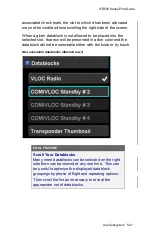
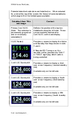
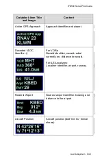
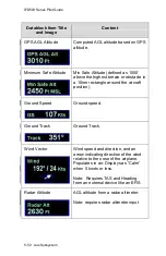
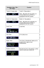
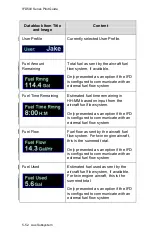
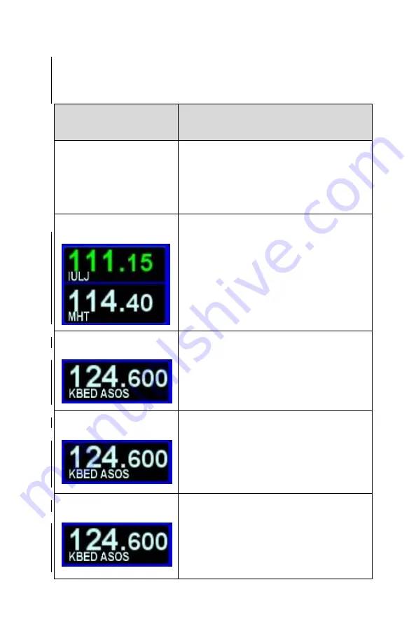
Potential datablock selections are listed below. When selected
for a slot at the top of the screen, the format of some datablocks
will change to fit in the limited space available.
Datablock Item Title
and Image
Content
Primary Com/VLOC
(Note: This selection is
permanently grayed out
and is not actually
selectable)
†
Defines the position of the top two
datablocks along the left side. These
are permanently dedicated to
Com/VLOC control and display.
VLOC Radio
†
Provides a means to display the Active
and Standby Nav frequencies in slots
3 and 4.
If Remote IFD Tuning is on, the
ide
ntifier will be preceded by “NAV1”
or “NAV2” signifying which radio is
being controlled
Com/VLOC Standby #2
†
Provides a means to display a third
com or nav frequency (second standby
slot)
Available only on the left side
Com/VLOC Standby #3
†
Provides a means to display a fourth
com or nav frequency (third standby
slot)
Available only on the left side
Com/VLOC Standby #4
†
Provides a means to display a fifth
com or nav frequency (fourth standby
slot)
Available only on the left side
Summary of Contents for IFD510
Page 1: ......
Page 140: ...IFD500 Series Pilot Guide 3 50 FMS Subsystem Weather Data on Info Tab Info Tab Nearby Navaids ...
Page 150: ...IFD500 Series Pilot Guide 3 60 FMS Subsystem User Waypoint Airfield Naming Example ...
Page 156: ......
Page 180: ...IFD500 Series Pilot Guide 4 24 Map Subsystem ADS B Lightning Coverage Area Shadow ...
Page 252: ...IFD500 Series Pilot Guide 5 16 Aux Subsystem Trip Statistics Calculator ...
Page 460: ...IFD500 Series Pilot Guide 7 82 General Bluetooth pairing pairing code ...

