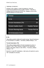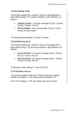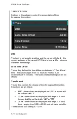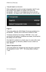
IFD500 Series Pilot Guide
5-60 Aux Subsystem
Visual Approach Settings
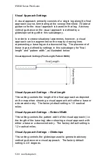
A visual approach primarily consists of a single leg along the final
approach course, terminating at the runway threshold. All lateral
guidance for the visual approach is based on that leg. Advisory
vertical guidance on the visual approach is defined by a
glideslope setting within this subcategory.
In order to increase situational awareness, however, a visual
approach can be augmented on the map by drawing lines
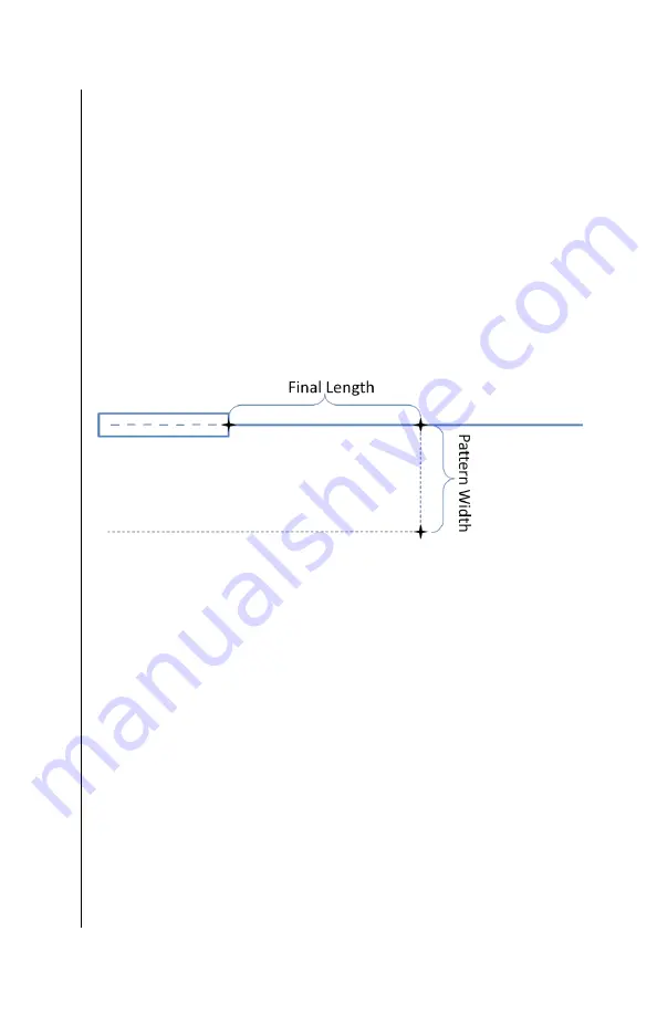
representing a base leg and a downwind leg. The placement of
those legs is defined by settings in this subcategory for “final
length” and “pattern width”, as illustrated below
Visual Approach Settings (Final Length, Pattern Width)
Visual Approach Settings
– Final Length
This setting controls the length of the final approach as depicted
on the map when showing a visual approach with either a base or
a downwind entry. The factory default setting is 1.0 nautical
miles.
Visual Approach Settings
– Pattern Width
This setting controls the pattern width of the visual approach (i.e.
the length of the base leg) when showing a visual approach with
either a base or a downwind entry. The factory default setting is
1.2 nautical miles.
Visual Approach Settings
– Glideslope
This setting controls the glideslope used to generate advisory
vertical guidance on a visual approach. The factory default
setting is 4.0 degrees.
Summary of Contents for IFD510
Page 1: ......
Page 140: ...IFD500 Series Pilot Guide 3 50 FMS Subsystem Weather Data on Info Tab Info Tab Nearby Navaids ...
Page 150: ...IFD500 Series Pilot Guide 3 60 FMS Subsystem User Waypoint Airfield Naming Example ...
Page 156: ......
Page 180: ...IFD500 Series Pilot Guide 4 24 Map Subsystem ADS B Lightning Coverage Area Shadow ...
Page 252: ...IFD500 Series Pilot Guide 5 16 Aux Subsystem Trip Statistics Calculator ...
Page 460: ...IFD500 Series Pilot Guide 7 82 General Bluetooth pairing pairing code ...

