background image

English

Table of Contents

Overview  . . . . . . . . . . . . . . . . . . . . . . . . . . . . . . . . . . 1

Front View   . . . . . . . . . . . . . . . . . . . . . . . . . . . . . . . . . . . .  1
Rear View  . . . . . . . . . . . . . . . . . . . . . . . . . . . . . . . . . . . . . 2

Installation . . . . . . . . . . . . . . . . . . . . . . . . . . . . . . . .  3

Required Tools and Materials  . . . . . . . . . . . . . . . . . . . . 3
Camera Package Contents   . . . . . . . . . . . . . . . . . . . . . . 3
Installation Steps  . . . . . . . . . . . . . . . . . . . . . . . . . . . . . . . 3

Mounting the Lens . . . . . . . . . . . . . . . . . . . . . . . . 4
Mounting the Camera . . . . . . . . . . . . . . . . . . . .   5
Connecting Cables  . . . . . . . . . . . . . . . . . . . . . .   6
Assigning an IP Address . . . . . . . . . . . . . . . . . .   6
Accessing the Live Video Stream . . . . . . . . . . . 7
Aiming and Focusing the Camera. . . . . . . . . . . 7
(Optional) Configuring Onboard Storage . . . .   8
For More Information. . . . . . . . . . . . . . . . . . . . .   9

Cable Connections . . . . . . . . . . . . . . . . . . . . . . . . .10

Connecting External Power  . . . . . . . . . . . . . . . . . . . . .  10
Connecting to External Devices  . . . . . . . . . . . . . . . . . . 11
Connecting to Microphones and Speakers   . . . . . . .  12

LED Indicators . . . . . . . . . . . . . . . . . . . . . . . . . . . . .13
Reset to Factory Default Settings   . . . . . . . . . . . .14
Setting the IP Address Through the 
ARP/Ping Method . . . . . . . . . . . . . . . . . . . . . . . . . .15
Cleaning   . . . . . . . . . . . . . . . . . . . . . . . . . . . . . . . . .16

Image Sensor  . . . . . . . . . . . . . . . . . . . . . . . . . . . . . . . . .  16
Body   . . . . . . . . . . . . . . . . . . . . . . . . . . . . . . . . . . . . . . . .  17

Specifications  . . . . . . . . . . . . . . . . . . . . . . . . . . . . .18
Limited Warranty & Technical Support  . . . . . . . .19

Summary of Contents for 12L-H4PRO-B

Page 1: ...Installation Guide Avigilon High Definition Professional IP Camera Models 16L H4PRO B 12L H4PRO B and 8L H4PRO B 920 0078A Rev1 ...

Page 2: ......

Page 3: ...on Installation must be performed by qualified personnel only and must conform to all local codes This product is intended to be supplied by a UL Listed Power Unit marked Class 2 or LPS or Limited Power Source with output rated 12 VDC or 24 VAC 10 W min or Power over Ethernet PoE rated 48 VDC 10 W min The Warning symbol indicates the presence of dangerous voltage within and outside the product enc...

Page 4: ...y or has been dropped Do not use strong or abrasive detergents when cleaning the device body Use only accessories recommended by Avigilon Use only UL listed mounting bracket suitable for the mounting surface and minimum 0 4 kg 0 9 lb weight plus the weight of the attached lens Avoid leaving the image sensor exposed for extended periods of time Always cover the image sensor with either a lens or a ...

Page 5: ...protection against such interference when operated in a commercial environment Operation of this equipment in a residential area is likely to cause interference in which case the user at his her own expense will be required to take whatever measures may be required to correct the interference Changes or modifications made to this equipment not expressly approved by Avigilon Corporation or parties ...

Page 6: ...pographical and other errors relating to the publication AVIGILON CAPTURE IT WITH CLARITY HDSM HIGH DEFINITION STREAM MANAGEMENT HDSM THE BEST EVIDENCE and LIGHTCATCHER are unregistered and or registered trademarks of Avigilon Corporation in Canada and other jurisdictions worldwide Other product names mentioned herein may be the unregistered and or registered trademarks of their respective owners ...

Page 7: ...sing the Live Video Stream 7 Aiming and Focusing the Camera 7 Optional Configuring Onboard Storage 8 For More Information 9 Cable Connections 10 Connecting External Power 10 Connecting to External Devices 11 Connecting to Microphones and Speakers 12 LED Indicators 13 Reset to Factory Default Settings 14 Setting the IP Address Through the ARP Ping Method 15 Cleaning 16 Image Sensor 16 Body 17 Speci...

Page 8: ...English ...

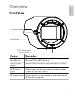
Page 9: ...se Button Releases the lens that is mounted on the camera EF S mount index A white mark on the lens mount to help you align an EF S lens to the camera EF mount index A red mark on the lens mount to help you align an EF lens to the camera Lens Mount Lens Release Button EF S mount index EF mount index ...

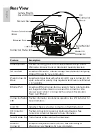
Page 10: ...urs over this connection Also receives power when it is connected to a network that provides Power over Ethernet Connection Status LED Provides information about device operation See LED indicators for more information Link LED Indicates if there is an active connection in the Ethernet port I O Connector Block Provides connections to external input output devices See Connecting to External Devices...

Page 11: ...he package contains the following Avigilon High Definition IP Camera Power terminal block Dust cap I O terminal block Installation Steps Complete the following procedures to install the camera 1 Mounting the Lens on page 4 2 Mounting the Camera on page 5 3 Connecting Cables on page 6 4 Assigning an IP Address on page 6 5 Accessing the Live Video Stream on page 7 6 Aiming and Focusing the Camera on...

Page 12: ...e used to prevent damage to the lens mount on the camera To mount a lens to the camera complete the following steps 1 If the lens includes a collar install the collar to the lens first 2 Remove the dust cap from the lens mount 3 Align the lens to the appropriate index marker on the lens mount Red mark EF mount index White mark EF S mount index 4 Turn the lens clockwise until it locks into place To...

Page 13: ...ever touch the image sensor or any glass elements inside the lens mount Only clean the image sensor with the recommended cleaning tools See Cleaning for more information Do not allow dust moisture or any other foreign debris to enter the lens mount Avoid leaving the image sensor exposed for extended periods of time Always cover the image sensor with either a lens or a dust cap Caution Always mount...

Page 14: ...or For more information see Connecting to Microphones and Speakers 3 Connect a network cable to the camera s Ethernet Port RJ 45 connector The Link LED will turn on once a network link has been established 4 Connect power using one of the following methods Power over Ethernet PoE Class 3 If PoE is available the camera LEDs will turn on External Power Connect an external 12 VDC or 24 VAC power sour...

Page 15: ...for example Avigilon Control Center NOTE The default camera username is admin and the default password is admin Accessing the Live Video Stream Live video stream can be viewed using one of the following methods Avigilon Camera Installation Tool software application Camera s web browser interface http camera IP address Network Video Management software application for example Avigilon Control Cente...

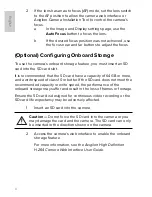
Page 16: ...t the SD card have a capacity of 64 GB or more and a write speed of class 10 or better If the SD card does not meet the recommended capacity or write speed the performance of the onboard storage may suffer and result in the loss of frames or footage Ensure the SD card is designed for continuous video recording or the SD card life expectancy may be adversely affected 1 Insert an SD card into the ca...

Page 17: ... the device is available in the following guides Avigilon Camera Installation Tool User Guide Avigilon Control Center Client User Guide Avigilon High Definition H 264 Web Interface User Guide The manuals are available on the Avigilon website http avigilon com support and downloads ...

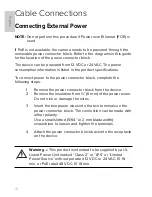
Page 18: ...ctor block complete the following steps 1 Remove the power connector block from the device 2 Remove the insulation from 6 mm of the power wires Do not nick or damage the wires 3 Insert the two power wires into the two terminals on the power connector block The connection can be made with either polarity Use a small slotted 5 64 or 2 mm blade width screwdriver to loosen and tighten the terminals 4 ...

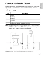
Page 19: ...nergize a relay coil with up to 200 mA If more than 200 mA is required an external power supply up to 25 VDC at 120 mA can be used Figure External I O schematics and example application Table External I O Connector Pin Description 1 Ground 2 RS 485B 3 RS 485A 4 Relay input 5 Relay output 6 5 VDC 200 mA max output for relay drive GND GND 3 3V GND 1 2 3 4 5 6 5 V 200 mA MAX 25 V 120 mA MAX B A RS 48...

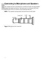
Page 20: ...d to an external microphone and speaker through the audio connector The connector is a mini jack 3 5 mm and the pinout for it is shown in the following diagram NOTE The camera only supports line level mono audio input Figure Mini jack audio connector Audio IN Audio OUT GND GND ...

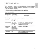
Page 21: ...Table LED Indicators Connection State Connection Status LED Description Obtaining IP Address One short flash every second Attempting to obtain an IP address Discoverable Two short flashes every second Obtained an IP address but is not connected to the Network Video Management software Upgrading Firmware Two short flashes and one long flash every second Updating the firmware Connected On Connected ...

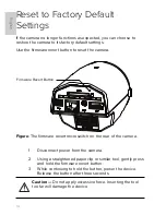
Page 22: ...amera Figure The firmware revert microswitch on the rear of the camera 1 Disconnect power from the camera 2 Using a straightened paperclip or similar tool gently press and hold the firmware revert button 3 While continuing to hold the button power the device Release the button after three seconds Caution Do not apply excessive force Inserting the tool too far will damage the device Firmware Revert...

Page 23: ...n the Serial Number Tag for reference 2 Open a Command Prompt window and enter the following commands a arp s New Camera IP Address Camera MAC Address For example arp s 192 168 1 10 00 18 85 12 45 78 b ping l 123 t New Camera IP Address For example ping l 123 t 192 168 1 10 3 Reboot the camera 4 Close the Command Prompt window when you see the following message Reply from New Camera IP Address ...

Page 24: ...ain an image sensor cleaning swab and solution Follow the cleaning instructions provided by the manufacturer Avigilon recommends using the Type 2 Sensor Swab and Eclipse cleaning solution made by Photographic Solutions Inc For a worldwide list of dealers visit the Photographic Solutions Inc website at www photosol com Caution Never touch the image sensor or any glass elements inside the lens mount...

Page 25: ...17 English Body Use a dry or lightly dampened cloth to clean the camera body Caution Do not use strong or abrasive detergents when cleaning the camera body ...

Page 26: ...SP HTTPS TCP HTTP Mechanical Dimensions L x W x H 109 mm x 73 mm x 68 mm 4 3 x 2 9 x 2 7 Weight 0 37 kg 0 8 lbs Camera Mount 20 UNC top and bottom Electrical Power Consumption 10 W camera only Power Source VDC 12 V 10 10 W VAC 24 V 10 14 3 VA PoE IEEE802 3af Class 3 compliant Power Connector 2 pin terminal block Environmental Operating Temperature 10 C to 50 C 14 F to 122 F Storage Temperature 10 ...

Page 27: ...ts distributors dealers agents or employees shall create another warranty or modify this warranty This warranty states Avigilon s entire liability and your exclusive remedy against Avigilon for any failure of this product to operate properly In no event shall Avigilon be liable for any indirect incidental special consequential exemplary or punitive damages whatsoever including but not limited to d...

Reviews: