Jump to: Table of Content
2022/04/11
Page : 22
Connector
Interface
Pin
Signal
Direction
WAGO A
2
nd
RS485
1
n.c.
Not connected
2
n.c.
Not connected
3
Signal B / D+
RS485 Bus
4
Signal A / D-
RS485 Bus
5
VCC (6..32V)
Power
6
GND
Power & Signal
WAGO B
1
st
RS485
1
n.c.
Not connected
2
n.c.
Not connected
3
Signal B / D+
RS485 Bus
4
Signal A / D-
RS485 Bus
5
VCC (6..32V)
Power
6
GND
Power & Signal
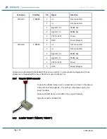
Cables are connected with the WAGO 734 series connectors. In most product configurations, those
adapters are shipped with the box. Check the 'scope of delivery' list.
5.5.4
Using the WAGO connector
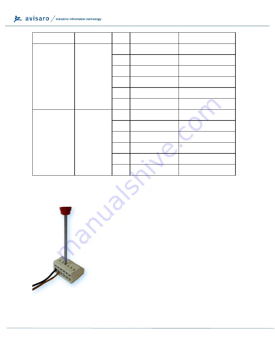
To open the WAGO clamp, insert a screwdriver as shown in the picture
to the left. Push down gently
–
this will open the clamp and you can
insert the cable.
Typically, WAGO clamp is included in the scope of delivery.
Type of connector: WAGO 734
5.5.5
1x RS485
“SILVER” ( “M41076”, “C41076” )


