background image

Important Information

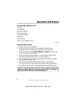
Recommended Installation Tools
Voltmeter

Wire Strippers
Electric Drill & Bits

Phillips Screwdriver
Convoluted Tubing *

Solder Gun *

Wire Crimpers
Shrink Tube or Electrical Tape

* Optional

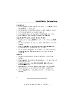
Recommended Procedures
1. Test all circuits with a voltmeter.

2. Make all wiring connections with the supplied solderless crimp

connectors. DO NOT twist wires or use scotch-lok connectors.

3. Route the small and large RED, RED/WHITE and BLACK wires from the

control unit directly to the battery.

4. Keep extensions as short as possible. Use same gauge wires for short

extensions and larger gauge wires for longer extensions.

5. Before installing, discuss the placement of the LED indicator and valet

switch with the vehicle owner.

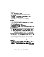
6. DO NOT disconnect the battery cables. Make all connections by

removing the bolts from the cable clamps without detaching the clamp.

7. Turn off dome light or remove dome light fuse to prevent battery drain.

This device complies with Part 15 of the FCC rules. Any changes or modifications
made to the system without the express approval of Avital Technologies, Inc.
could void the user’s authority to operate this equipment.

2

AviStart 4500 Installation Manual - 0898 Rev. A

Summary of Contents for AviStart 4500

Page 1: ...AviStart 4500 Installation Manual 0898 Rev A ...

Page 2: ...AviStart 4500 Installation Manual 0898 Rev A ...

Page 3: ...t Illumination 8 Trunk Release 8 Channel 5 Accessory 8 Remote Start Armed Signal Output 9 Siren Horn Output Remote Panic Capability 9 Factory Alarm Disarm Output 9 Accessory Remote Start Input 9 Ignition Switch Connections 9 Remote Engine Start Neutral Safety Switch Bulletin 11 Door Lock Unlock 14 Door Lock Unlock Diagrams 14 Tach Wire RPM Monitoring 18 Hood Switch Mandatory 18 Power and Ground Co...

Page 4: ... Keep extensions as short as possible Use same gauge wires for short extensions and larger gauge wires for longer extensions 5 Before installing discuss the placement of the LED indicator and valet switch with the vehicle owner 6 DO NOT disconnect the battery cables Make all connections by removing the bolts from the cable clamps without detaching the clamp 7 Turn off dome light or remove dome lig...

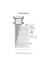
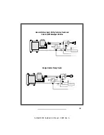
Page 5: ...3 AviStart 4500 Installation Manual 0898 Rev A Main Wiring Diagram ...

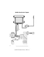
Page 6: ...4 AviStart 4500 Installation Manual 0898 Rev A Satellite Relay Module Diagram ...

Page 7: ...everse Light Input 12 WHITE LIGHT Tachometer Input 13 RED WHITE Parking Light Polarity Input or Select 14 RED BLACK Parking Light Output 15 RED Battery 16 WHITE BLACK Door Trigger Input Polarity or Select 17 BLACK Battery 18 VIOLET Siren Horn Output 19 GREEN BLACK Unlock Switch Side 20 GREEN WHITE Unlock Motor Side 21 GREEN RED Unlock Polarity or Select 22 BLUE BLACK Lock Switch Side 23 BLUE WHITE...

Page 8: ...possible 3 Route the antenna cable up through the driver side windshield pillar behind the headliner and behind the rear view mirror 4 Use the small mounting tabs to connect the antenna to the windshield behind the rear view mirror approximately 2 below the top of the windshield Wireloom 1 Plug the wirelooms securely into the control unit and satellite relay module 2 Route wires from the control m...

Page 9: ...onnect the RED WHITE wire to the control unit RED wire Continued on next page 7 AviStart 4500 Installation Manual 0898 Rev A LED Indicator 1 Discuss placement with the owner 2 Choose a location that is visible from both sides of the vehicle 3 Drill a hole 4 Route the LED wires through the hole and press LED into place 5 Route the LED wires to the control unit 6 Plug the RED LED connector into the ...

Page 10: ...HITE wire to the vehicle door trigger wire 2 If the door trigger is negative connect the WHITE BLACK wire to ground 3 If the door trigger wire is positive switching connect the WHITE BLACK wire to a fused constant 12 volt source Trunk Release The DARK BLUE wire provides a 0 75 second ground output when the TRUNK button is pressed for 1 2 seconds If the TRUNK button is continually pressed the outpu...

Page 11: ...locate the one wire that will show ground only when the driver door key cylinder is held in the unlock position NOTE Most factory alarm disarm wires will show 8 12 volts while armed A few vehicle disarm wires will rest at a neutral state while armed Regardless of type both types will change to ground when the key cylinder is turned to unlock 3 Connect the GRAY WHITE wire to the factory alarm disar...

Page 12: ...st be added Do not use the GRAY wire to power more than one heater AC wire 1 Use a voltmeter to find the wire s that show 12 volts when the ignition key is in the ON position 0 volts while the starter is cranking and 12 volts while running 2 Cut this wire in half Start the vehicle and turn the blower switch on The blower should not turn on 3 Connect the GRAY wire to the heater AC wire Starter I WA...

Page 13: ...h and the neutral safety switch Type B combined Some vehicles combine the neutral safety switch and the steering column shift mechanism together The starter wires run from the combined switch directly to the starter solenoid The remote start wire connection cannot be made between the ignition switch and the neutral safety switch As a result if the vehicle was left in gear with the key in the ignit...

Page 14: ...prepared to step on the brake if the starter engages 5 Activate the remote engine starter 6 If the vehicle starter engages immediately press the brake pedal to disengage shut down the remote start You have a combined type neutral safety switch and you will have to add an additional relay as shown in the diagram 7 If the vehicle starter does not engage no additional relays are required All vehicles...

Page 15: ...General Motors Sport Utility Vehicles Trucks and Column Shift Passenger Vehicles Dodge Dakota Pickup Trucks 13 AviStart 4500 Installation Manual 0898 Rev A ...

Page 16: ...on Manual 0898 Rev A Door Lock Unlock The system has onboard door lock relays to lock and unlock all of the doors as well as a two stage unlock The diagrams on pages 14 17 will illustrate standard lock unlock and two stage unlock ...

Page 17: ...15 AviStart 4500 Installation Manual 0898 Rev A ...

Page 18: ...16 AviStart 4500 Installation Manual 0898 Rev A ...

Page 19: ...17 AviStart 4500 Installation Manual 0898 Rev A ...

Page 20: ...a wire that will show 1 to 5 volts AC while the vehicle is idle and increase an additional 1 to 5 volts AC when the engine RPM is raised to 3000 4000 RPM 3 Connect the WHITE GREEN wire to the vehicle tach wire Hood Switch Mandatory As a safety precaution the hood switch prevents the vehicle from starting when the hood is open If the vehicle is in the remote start mode and the hood is opened the re...

Page 21: ...nected correctly 11 Install the 5 amp fuse in the 18 ga RED wire fuse assembly 12 Install the 20 amp fuse in the RED WHITE wire fuse assembly 13 Install the two 20 amp fuses in the 10 ga RED wire fuse assemblies Mandatory RPM Programming In order to remote start the vehicle engine and prevent over grinding of the starter motor the engine RPM must be programmed into the system memory The AviStart h...

Page 22: ...dicated by the LED on solid red 2 Select the feature you wish to program from the Programming Table for System Features or the Programming Table for Remote Controls on pages 21 22 Note the number of beeps associated with that feature 3 Turn the ignition key to the ON position 4 Within 10 seconds begin flicking the valet switch on and off The built in piezo beeper will beep once each time you flick...

Page 23: ...ds the piezo beeper will beep once for OFF twice for ON Remote Lock Starter Disable ON 10 Wait 3 seconds the piezo beeper will beep once for OFF twice for ON Horn Siren Output Horn 11 Wait 3 seconds the piezo beeper will beep once for Siren twice for horn Mandatory RPM Programming 12 See Mandatory RPM Programming on page 19 Remote Start Run Time 20 or 30 Minutes 20 Minutes 13 Wait 3 seconds the pi...

Page 24: ...TRUNK Button 20 Press the TRUNK Button the p iezo beeper will beep 4 times Temperature Controlled Start Active Inactive LOCK START Buttons 21 Press the LOCK START Buttons the piezo beeper will beep 5 times Remote Accessory Output LOCK UNLOCK Buttons 22 Press the LOCK UNLOCK Buttons the piezo beeper will beep 6 times One Step Remote Control Code Learning LOCK Button 23 Press the LOCK Button the pie...

Reviews: