9
The following 'jumper' connections on the AVR should be
checked to ensure they are correctly selected for the
generating set application:
1) Frequency selection
Ufro switch position selected to suit operating frequency.
Initial Switch
Postion
4P/50Hz corresponds to1500 r.p.m.
4
4P/60Hz corresponds to1800 r.p.m.
5
Switch position to be optimised during commissioning.
2) Stability selection
Stability selection switch - select position 6.
4.5 GENERATOR SET TESTING
Fig. 1
4.5.1 TEST METERING/CABLING
Warning!
During testing it may be necessary to
remove covers to adjust controls
exposing 'live' terminals or components.
Only personnel qualified to perform
electrical service should carry out
testing and/or adjustments.
Connect any instrument wiring and cabling required for initial
test purposes with permanent or spring-clip type connectors.
Minimum instrumentation for testing should be line to line or
line to neutral voltmeter, Hz meter, load current metering and
kW meter. If reactive load is used a power factor meter is
desirable.
Important!
When fitting power cables for load testing
purposes, ensure cable voltage rating is at
least equal to the generator rated voltage.
Support the cables to prevent side load
on the terminal.
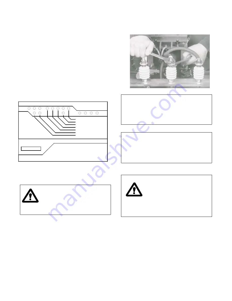
The load cable termination should be placed on top of the
winding lead termination and clamped between the two nuts
provided, as shown below.
Caution!
MV/HV LOAD CABLE TERMINATION
Extending the load terminals by
means of an extension bar may
cause excessive side loads on the
ceramic terminal insulators and should
be avoided.
Caution!
Check that all wiring terminations
for internal or external wiring are
secure, and fit all terminal box
covers and guards. Failure to secure
wiring and/or covers may result in
personal injury and/or equipment failure.
4.6 INITIAL START-UP
Warning!
During testing it may be necessary to
remove covers to adjust controls
exposing 'LIVE' terminals or
components. Only
personnel
qualified to perform electrical service
should carry out testing and/or
adjustments.
Refit all access covers after
adjustments are completed.
On completion of generating set assembly and before
starting the generating set ensure that all engine
manufacturer's pre-running procedures have been
completed, and that adjustment of the engine governor is
such that the generator will not be subjected to speeds in
excess of 125% of the rated speed.
Important!
Overspeeding of the generator
during initial setting of the speed
governor can result in damage to
the generator rotating components.
A2
Automatic Voltage Regulator
Dwell
NEWAGE
INTERNATIONAL
6
S1
8
7
S2
0v
2
1
A1
Volts
UFRO
Stab
Part No. E000-13270
E4
E3
Ramp
UFRO Select 50/60Hz
Stability Select
Droop
Trim
Dip
Mode
Exc
PWL
O/V
Hand


