A-Series Dobby Loom Assembly Manual
Side Frame Assembly
Complete the side frame
1)
2)
3)
Note:
The end of the front vertical (
attached to the
If this is done correctly, the two small holes
on the top as shown in the side frame drawings.
4)
5)
Figure
6)
7)
Add the
The Dobby Cam and Pulley assembly will be plac
between the #9 supports. This assembly allows the treadles or e
Series Dobby Loom Assembly Manual
Side Frame Assembly
Complete the side frame
Find the
base with
5½”long
Find the
base with one 5/16" x 5" bolt through the
Find the
bolts through th
The end of the front vertical (
attached to the
If this is done correctly, the two small holes
on the top as shown in the side frame drawings.
Find the
of the rear vertical (
Attach it to the castle (#5) with a 5 ½” bolt.
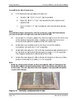
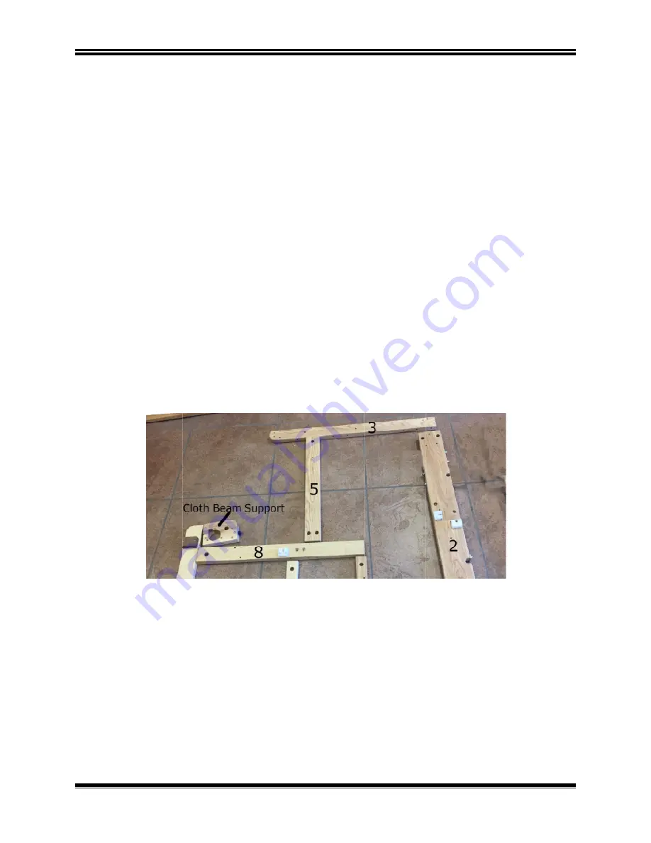
Figure 18 - Top of side frame
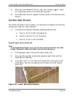
Place the cloth beam support on the pin in the lower cloth beam
support (#8).
Attach the cloth beam support to the front vertical (#1) with a 5 ½”
bolt.
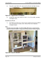
Add the Dobby Cam and Pulley
The Dobby Cam and Pulley assembly will be plac
between the #9 supports. This assembly allows the treadles or e
Series Dobby Loom Assembly Manual
Side Frame Assembly
Complete the side frame
the lower cloth
with one bolt
5½”long bolt in eac
Find the upper cloth beam support (
with one 5/16" x 5" bolt through the
Find the castle (#
bolts through the lower cloth beam
The end of the front vertical (
attached to the castle (#
If this is done correctly, the two small holes
on the top as shown in the side frame drawings.
Find the top horizontal
rear vertical (
Attach it to the castle (#5) with a 5 ½” bolt.
Top of side frame
Place the cloth beam support on the pin in the lower cloth beam
support (#8).
Attach the cloth beam support to the front vertical (#1) with a 5 ½”
Dobby Cam and Pulley
The Dobby Cam and Pulley assembly will be plac
between the #9 supports. This assembly allows the treadles or e
Series Dobby Loom Assembly Manual
Complete the side frame
cloth beam
bolt through
bolt in each of the side supports (
er cloth beam support (
with one 5/16" x 5" bolt through the
#5). Attach
e lower cloth beam
The end of the front vertical (#1) with the number stamp on it must be
#5) with one bolt, with the number stamp facing down.
If this is done correctly, the two small holes
on the top as shown in the side frame drawings.
horizontal (#3
rear vertical (#2) with two bolts.
Attach it to the castle (#5) with a 5 ½” bolt.
Top of side frame
Place the cloth beam support on the pin in the lower cloth beam
Attach the cloth beam support to the front vertical (#1) with a 5 ½”
Dobby Cam and Pulley (#20)
The Dobby Cam and Pulley assembly will be plac
between the #9 supports. This assembly allows the treadles or e
support (#
through the front
h of the side supports (
er cloth beam support (
with one 5/16" x 5" bolt through the
Attach it into the
e lower cloth beam support
1) with the number stamp on it must be
) with one bolt, with the number stamp facing down.
If this is done correctly, the two small holes
on the top as shown in the side frame drawings.
3). Using 5 ½” bolts, a
) with two bolts.
Attach it to the castle (#5) with a 5 ½” bolt.
Place the cloth beam support on the pin in the lower cloth beam
Attach the cloth beam support to the front vertical (#1) with a 5 ½”
(#20)
The Dobby Cam and Pulley assembly will be plac
between the #9 supports. This assembly allows the treadles or e
#8) and a
front vertical (
h of the side supports (#9
er cloth beam support (#10) and a
with one 5/16" x 5" bolt through the front vertical
the side frame
support (#
1) with the number stamp on it must be
) with one bolt, with the number stamp facing down.
If this is done correctly, the two small holes on the top horizontal
on the top as shown in the side frame drawings.
Using 5 ½” bolts, a
) with two bolts.
Attach it to the castle (#5) with a 5 ½” bolt.
Place the cloth beam support on the pin in the lower cloth beam
Attach the cloth beam support to the front vertical (#1) with a 5 ½”
The Dobby Cam and Pulley assembly will be placed in the right side frame
between the #9 supports. This assembly allows the treadles or e
and attach it to
(#1) and with
9).
and attach it
front vertical
side frame with two
#8).
1) with the number stamp on it must be
) with one bolt, with the number stamp facing down.
on the top horizontal
Using 5 ½” bolts, attach it
Place the cloth beam support on the pin in the lower cloth beam
Attach the cloth beam support to the front vertical (#1) with a 5 ½”
ed in the right side frame
between the #9 supports. This assembly allows the treadles or e
Frame Assembly
Page |
to the side
1) and with a
to the side
front vertical (#1).
with two 5½ long
1) with the number stamp on it must be
) with one bolt, with the number stamp facing down.
on the top horizontal (#3) will be
it to the top
Place the cloth beam support on the pin in the lower cloth beam
Attach the cloth beam support to the front vertical (#1) with a 5 ½”
ed in the right side frame
between the #9 supports. This assembly allows the treadles or e-lift to
Frame Assembly
Page | 19
side
side
5½ long
) with one bolt, with the number stamp facing down.
) will be
top
Place the cloth beam support on the pin in the lower cloth beam
Attach the cloth beam support to the front vertical (#1) with a 5 ½”
ed in the right side frame

