Appendices
Page 62
APPENDIX C: Jacq3G Module Troubleshooting and Adjusting Guide (continued)
Lubrication: See Jacq3G Lubrication Schedule document.
Knife alignment:
1)
Knife angle: If the angle of a knife is observably different from the neighboring modules it must be remedied before any further loom use.
Failure to do so will cause bearing failure. The knife angle and knife height alignment procedures are the same -- see below.
2)
Knife height: Knife alignment procedure requires that the heddle springs be released from the anchors at the bottom of the loom and that
the loom be at center shed. Once complete, reconnect the springs and reset the shedding programming to double shed.
a)
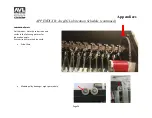
Upper knife angle adjustment: Loosen the button head cap screws for the drive cable clamps mounted to the knife. The upper knife
should slide smoothly without damaging the cable sheathing. Slide the knife until the front and rear inner bearing carriers are in contact
with the hardware at the bottom of it bearing travel. If the outer bearing carrier touches the hardware first, apply additional force to
overcome the inner to outer carrier force until the inner bearing carrier is in the correct position. Retighten the button head cap screws.
b)
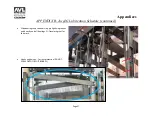
Lower knife angle adjustment: Loosen the button head cap screws for the drive cable clamps mounted to the knife. The lower knife
should slide smoothly without damaging the cable sheathing. Slide the lower knife until the front and rear inner bearing carriers are ¾”
from the hardware at the top of it bearing travel. If the outer bearing carrier is hitting the hardware and preventing the inner carrier
from reaching the measurement, apply additional force to overcome the inner to outer carrier force until the inner bearing carrier is in
the correct position (¾” from the hardware at the top of it bearing travel). Retighten the button head cap screws.
Summary of Contents for TECHNICAL EDUCATION LOOM
Page 27: ...Loom Manual Page 27 Cloth Clamp Closed Cloth Clamp Open Fixed Clamp Open Fixed Clamp Hanging ...
Page 29: ...Loom Manual Page 29 Module Hooks Exposed Front Cover Removed Hooks Close Up ...
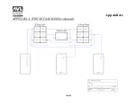
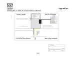
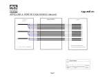
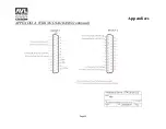
Page 33: ...Appendices Page 33 APPENDIX A WIRING DIAGRAMS continued ...
Page 34: ...Appendices Page 34 APPENDIX A WIRING DIAGRAMS continued ...
Page 35: ...Appendices Page 35 APPENDIX A WIRING DIAGRAMS continued ...
Page 36: ...Appendices Page 36 APPENDIX A WIRING DIAGRAMS continued ...
Page 37: ...Appendices Page 37 APPENDIX A WIRING DIAGRAMS continued ...
Page 38: ...Appendices Page 38 APPENDIX A WIRING DIAGRAMS continued ...
Page 39: ...Appendices Page 39 APPENDIX A WIRING DIAGRAMS continued ...
Page 40: ...Appendices Page 40 APPENDIX A WIRING DIAGRAMS continued ...
Page 41: ...Appendices Page 41 APPENDIX A WIRING DIAGRAMS continued ...
Page 42: ...Appendices Page 42 APPENDIX A WIRING DIAGRAMS continued ...
Page 43: ...Appendices Page 43 APPENDIX A WIRING DIAGRAMS continued ...
Page 44: ...Appendices Page 44 APPENDIX A WIRING DIAGRAMS continued ...
Page 45: ...Appendices Page 45 APPENDIX A WIRING DIAGRAMS continued ...
Page 46: ...Appendices Page 46 APPENDIX A WIRING DIAGRAMS continued ...
Page 47: ...Appendices Page 47 APPENDIX A WIRING DIAGRAMS continued ...
Page 48: ...Appendices Page 48 APPENDIX A WIRING DIAGRAMS continued ...
Page 49: ...Appendices Page 49 APPENDIX A WIRING DIAGRAMS continued ...
Page 50: ...Appendices Page 50 APPENDIX A WIRING DIAGRAMS continued ...
Page 51: ...Appendices Page 51 APPENDIX A WIRING DIAGRAMS continued ...
Page 52: ...Appendices Page 52 APPENDIX A WIRING DIAGRAMS continued ...
Page 53: ...Appendices Page 53 APPENDIX A WIRING DIAGRAMS continued ...
Page 54: ...Appendices Page 54 APPENDIX A WIRING DIAGRAMS continued ...

