Model 1200K/1210K - RCI SNG ANTENNA SYSTEM
11
Operation and Maintenance Manual
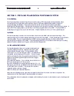
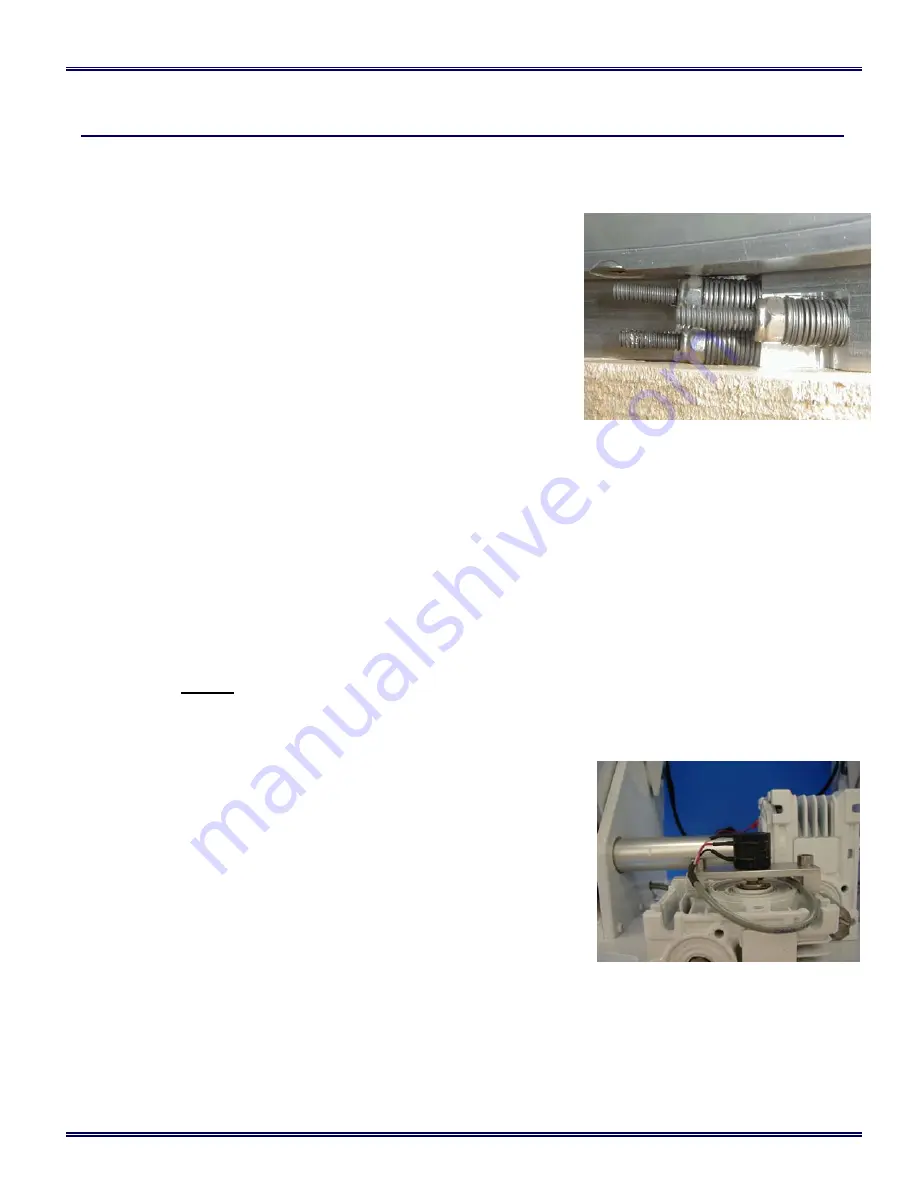
Figure 3.4
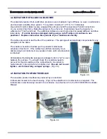
3.4 AZIMUTH ROTO-LOK® CABLE DRIVE
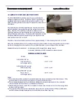
The patented azimuth Roto-Lok® drive produces a drive system
with zero backlash, high stiffness, no wear, no lubrication, and
maximum reliability. The system consists of three or four 1/16, 7 x
19 stainless steel aircraft control cables reverse wrapped twice
around the grooved capstan and once around the drum, with solid
connections on one end and high force, Belleville springs on the
other end (Fig 3.3.) One cable has the capacity to withstand a 75
mph wind load. The additional cables are used to provided
increased stiffness and drive redundancy.
If a cable becomes
damaged during usage, cut off cable and continue to use
positioner. Replace cable when time permits at your
maintenance facility.
The cables are sized to last the life of the positioner. The springs
will automatically compensate for
any elongation of the cable.
Cable position should be checked as per the periodic maintenance schedule in Section 7. If cables
have drifted, manually move cables using blunt instrument on azimuth drum until correct position is
obtained.
At installation the Belleville springs are collapsed until no “air” is seen between the springs. You
should check this condition yearly to account for the slow settling of the cable strands. Use pliers
to hold stud and ¼ box end wrench to tighten nut.
Be sure not to over tighten. Tighten until
springs are almost fully collapsed.
(Fig 3.3)
3.5 AZIMUTH POSITION FEEDBACK
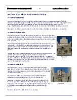
The azimuth position feedback is produced by a 10 turn, 1K-ohm
potentiometer driven by the output shaft of the worm gear box. (Fig
3.4) Since the Roto-Lok drive has no backlash, the position feedback
is as accurate (1%) as the resolution (.3°) and accuracy of the
potentiometer and the backlash between the potentiometer and the
azimuth capstan. The potentiometer is sealed and rated for IP 65
environment - wind, rain, dust, etc.
The potentiometer is mounted on a bracket that straddles the az gear
box. The azimuth potentiometer is slotted and driven with a cross pin
in the az capstan. The potentiometer is mechanically centered at the
travel position ( 5 turns from either end ) when az platform is in the az
stow position. This is accomplished by loosening the ½” nut, which
secures the potentiometer to the bracket. The potentiometer may
also be electrically zeroed by the controller. See Section 2.3
in the RCI 3000/3050 Controller manual.
Figure 3.3


