background image

Model 1200K/1210K - RCI SNG ANTENNA SYSTEM

3

Operation and Maintenance Manual

SECTION 1 - OVERVIEW

TECHNICAL DESCRIPTION

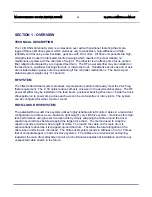
The 1.2M SNG Antenna System is an elevation over azimuth positioner featuring the simple,
rugged Roto-Lok® drive system which produces very low backlash, high-stiffness and high-
reliability and driven by a low backlash, gear box with DC motors.  All drive components are high-
strength steel, housed in lubricated-for-life housings which results in the most reliable, no
maintenance system with the minimum of weight.  The reflector is an offset, prime focus, carbon
fiber reflector illuminated by a corrugated feed horn.  The RF power amplifier may be installed on
the feed boom, positioner backing structure or inside the truck.  Handcranks across az and el axis
are included allowing easy antenna positioning if the controller malfunctions.  The basic 2-port
antenna system weighs only 117 pounds.

RF SYSTEM

The offset reflector/feed system produces co-polarization patterns that easily meet the 29-25 log
theta requirement.  The .8 f/d optics reduces off-axis cross-pol in the asymmetrical plane.  The RF
power amplifier may be installed on the feed boom, positioner backing structure or inside the truck. 
Waveguide run to power amp across each axis can be via twist-flex or rotary joints.  The system
can be configured for either 2-port or 4-port.

ROTO-LOK® DRIVE SYSTEM

The patented Roto-Lok® drive system utilizes highly-reliable aircraft control cables in a redundant
configuration to achieve a zero-backlash, light-weight, very stiff drive system.  It achieves this high-
tech performance using low-tech components by simply wrapping the cable around the driver
capstan several times before wrapping the larger drive drum.  The method used to wrap the
capstan results a minimum free-length of cable.  The load in the cable on the main drum is
exponentially reduced as it is wrapped around the drum.  Therefore the total elongation of the
cable when under load is minimized.  The Roto-Lok® system results in stiffness of up to 10 times
that of comparable gear or harmonic drive systems.  The cables are pre-tensioned and spring-
loaded at the main drum attachment point, which eliminates backlash at installation and from any
unexpected cable stretch in the future.

Summary of Contents for 1200K

Page 1: ...L Technologies P 130 Roberts Street P Asheville NC 28801 828 250 9950 P 828 250 9938 Fax P www avltech com Copyright 2006 No part of this document may be photocopied or otherwise reproduced without the prior permission in writing of AvL Technologies Inc Such written permission must also be obtained before any part of this document is stored in an electronic system of whatever nature ...

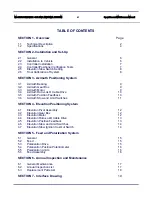
Page 2: ...ok Cable Drive 10 3 5 Azimuth Position Feedback 10 3 6 Azimuth Stow and Limit Switches 11 SECTION 4 Elevation Positioning System 4 1 Elevation Pivot Assembly 12 4 2 Elevation Gear Box 12 4 3 Elevation Motor 12 4 4 Elevation Roto Lok Cable Drive 13 4 5 Elevation Position Feedback 13 4 6 Elevation Stow and Limit Switches 14 4 7 Elevation Stow Ignition Cut Out Switch 14 SECTION 5 Feed and Polarizatio...

Page 3: ...ment The 8 f d optics reduces off axis cross pol in the asymmetrical plane The RF power amplifier may be installed on the feed boom positioner backing structure or inside the truck Waveguide run to power amp across each axis can be via twist flex or rotary joints The system can be configured for either 2 port or 4 port ROTO LOK DRIVE SYSTEM The patented Roto Lok drive system utilizes highly reliab...

Page 4: ...e the best torque to weight ratio as well as allowing dual speed operation for slewing and peaking These motors produce constant torque over the speed range with no cogging at low speeds which ensures smooth operation when peaking antenna The 24V DC design provides current limiting torque control and will allow vehicle battery operation if necessary CONTROLS The system will interface with a jog co...

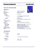
Page 5: ...eploying 2 second Peaking 0 2 second Motors 24V DC Variable Speed Constant Torque RF Interface HPA Storage Feed Boom Rear of Reflector or Inside Truck Axis Transition Twist Flex or Rotary Joints Waveguide WR 75 Cover Flange at Interface Point Coax RG59 run from feed to base plus 8 ft Electrical Interface 25 ft Cable with Connectors for Controller Optional Manual Drive Hex Socket Wrench Weight 110 ...

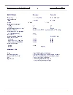
Page 6: ...ing Antenna Noise Temperature 30 Elevation Angle 30 K Polarization Linear Power Handling Capability 0 5KW per port Cross Pol Isolation On Axis 35 dB 35 dB Off Axis within 5 dB BW 32 dB 32 dB Off Axis within 1 dB BW 30 dB 30 dB Feed Port Isolation RX RX 30 dB TX RX 60 dB CONTROLLER Type Jog or Full Function Controller Manual Mode Input Front Panel Keypad for Jog Run Run To Stow Automatic Mode Input...

Page 7: ...gh to prevent no more than a 0 5 dB of TX gain loss in a 30 mph gusting to 45 mph wind 850 IN LB moment 25 A 11 inch diameter hole should be in the mounting surface The mounting surface must be flat within 005 inch to prevent binding the azimuth bearing after torquing the mounting bolts No obstruction should be above the interface surface in a 17 inch diameter envelope Any other roof mounted equip...

Page 8: ...o cure before final torquing IF INTERFACE SURFACE IS FLAT WITHIN 005 INCH apply a thin coat of silicone between azimuth ring and surface TORQUE ALL 12 BOLTS TO 9 10 FT LBS 2 3 CONTROLLER INSTALLATION Install controller into electronics rack Connect cables to rear making sure P1 and P2 are connected to correct sockets P1 to J1 and P2 to J2 Confirm controller voltage and fuse are correct if not conv...

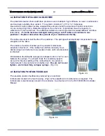
Page 9: ...ATED SO ANTENNA MOVEMENT MAY BE OBSERVED DURING TEST Press mode key to change screens and Select STOW Watch reflector surface approach feed horn Press STOP when reflector is within 2 of feed horn Jog down until reflector presses on rubber padding on feed housing Adjust stow limit switch if necessary by bending lever Stow switch is on east side with long lever East is the left side as viewed from b...

Page 10: ...th capstan is secured to the output shaft with a square key knurl plus permanent locktite to eliminate any backlash between the capstan and gearbox The low backlash is achieved by selective fit of the worm and worm gear The nominal backlash for the gearbox is 30 which is reduced by the Roto Lok drive to less than 4 of the beam of the antenna The gearbox contains synthetic oil filled half way to th...

Page 11: ... correct position is obtained At installation the Belleville springs are collapsed until no air is seen between the springs You should check this condition yearly to account for the slow settling of the cable strands Use pliers to hold stud and box end wrench to tighten nut Be sure not to over tighten Tighten until springs are almost fully collapsed Fig 3 3 3 5 AZIMUTH POSITION FEEDBACK The azimut...

Page 12: ...e stow switch the az stow position can be varied by either changing the zero position of the az potentiometer or zero voltage of the controller Rotation Direction Convention is clockwise CW viewed from above mount is counter clockwise CCW viewed from above mount NOMINAL AZIMUTH LIMITS Model Limits 1200 With 300 az and no az RJ or 145 155 with single az RJ 1200 With 270 az and With dual az RJ 120 1...

Page 13: ...ole and square key The worm shaft is extended with a hex shape adapter for the hand crank The dual elevation capstans are driven with a square key and clamped to the gearbox shaft to eliminate backlash Fig 4 2 The gearbox contains synthetic oil filled half way to the level plugs Because of the design capacity of the gearbox low rpm and limited cycles experienced by an SNG system no maintenance is ...

Page 14: ...y The cables are sized to last the life of the positioner The springs will automatically compensate for any elongation of the cable The position should be checked per the periodic maintenance schedule in Section 6 If the cables have drifted manually move cables using blunt instrument on elevation drums until correct position is obtained At installation the Belleville springs are collapsed until no...

Page 15: ...rum side plates The elevation up and down switches do not require adjustment The Elevation Stow switch is adjusted by using needle nose pliers and bending the limit switch lever as needed See section 2 6 above 4 7 ELEVATION STOW IGNITION CUT OUT SWITCH A second elevation stow switch is mounted on the west elevation pivot and used as an ignition cutout switch It should be adjusted to actuate before...

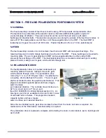
Page 16: ... screws at the rear flange of the OMT The feed polarization drive is mounted underneath pol mounting plate with worm mating to worm gear which extends through slot 5 3 POLARIZATION DRIVE The feed polarization drive is mounted underneath pol mounting plate with a worm mating to the worm gear which extends through a slot The polarization drive motor Fig 5 1 is a 12V DC gear motor It is attached to a...

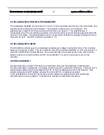
Page 17: ...voltage to determine limits The controller drives to 0 pol when it stows The AvL positioner has the mechanical capability of 92 per section 3 3 of the RCI 3000 3050 Controller Manual If the controller fails to terminate power to the motor and the system is driven to a hard limit stop the DC motor will stall To correct reset pol jam error in the controller 5 6 FEED ASSEMBLY The feed assembly consis...

Page 18: ...hten springs if more than 010 gap exists between spring sets Tighten With an open end wrench and using Visegrip pliers holding stud Inspect az stow switch Inspect and confirm az potentiometer is seated properly and not damaged Check az bearing screws az gearbox bolts az pot bracket etc are tight ELEVATION Hand cranking in elevation the unit should hand crank easily Unit should hand crank with appr...

Page 19: ... environmental exposure Description Manufacture Manufacture Part No Limit Switch Short Arm Omron D2VW 5L2A 1HS Limit Switch Long Arm Omron D2VW 5L2 1HS Potentiometer 1k 10T ETI MW20B 2982 1K Clinometers Lucas 02111 002 000 Optional AZ EL Rotary Joint Advanced Microwave AMC 206 CG CG RJ U B WR75 Super flex 18 Microtech MTES75 502 N 18B Elevation Motor Colman CYMA 82700 721 Azimuth Motor Colman CYMA...

Page 20: ...Model 1200K 1210K RCI SNG ANTENNA SYSTEM 20 Operation and Maintenance Manual SECTION 7 INTERFACE DRAWING ...

Page 21: ...Model 1200K 1210K RCI SNG ANTENNA SYSTEM 21 Operation and Maintenance Manual ...

Reviews: