Model 1200K/1210K - RCI SNG ANTENNA SYSTEM
8
Operation and Maintenance Manual
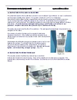
Remove the bolts attaching the positioner to the shipping base. Adjust the forks on a forklift to just
straddle the azimuth ring and under the elevation pivot assemblies.
Place cardboard pieces between
the positioner and the forks.
Carefully raise positioner out of crate watching control cables. Safety strap positioner to forklift
truck. Maneuver over to rear of truck. Raise positioner to clear vehicle roof by about two feet.
Lower control cables into center of mounting hole and install ¼ - 20 x 1" long screws (provided)
into holes in azimuth ring diametrically opposed. Use these as guides to position azimuth ring
directly over bolt circle.
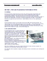
Note: Positioner must be installed with azimuth cable termination housing
aligned on centerline of vehicle.
(Fig. 2.2)
Remove and replace set screws with mounting bolts provided.
APPLY LOCKTITE 242 OR EQUIVALENT TO BOLTS.
IF INTERFACE SURFACE IS NOT FLAT WITHIN .005 INCH,
apply a thin layer of structural epoxy grout
between azimuth ring and vehicle surface. Snug bolts finger tight and allow epoxy to cure before final
torquing .
IF INTERFACE SURFACE IS FLAT WITHIN .005 INCH,
apply a thin coat of silicone between
azimuth ring and surface.
TORQUE ALL 12 BOLTS TO 9 - 10 FT. LBS.
2.3 CONTROLLER INSTALLATION
Install controller into electronics rack. Connect cables to rear making sure P1 and P2 are connected
to correct sockets. (P1 to J1 and P2 to J2)
Confirm controller voltage and fuse are correct,
if not
convert to correct voltage by following instructions in the RCI 3000/3050 Controller manual Section 2.2.1.
Connect AC power cable to controller.
2.4 CONTROLLER / POSITIONER VERIFICATION TEST
Turn power on. Wait for self-check to complete. Hit mode button once to reach display/function
mode. Press deploy button to Deploy. Antenna will drive until:
ELEVATION
20.0° (approx)
AZIMUTH
0.0°
POLARIZATION
0.0°
Press speed button to change speed to FAST
HAVE SOMEONE OUTSIDE AND ELEVATED SO ANTENNA MOVEMENT CAN BE OBSERVED
DURING TEST
!
Push El UP button. Antenna elevation reading should increase. Move until elevation reads 20°.
Place inclinometer on feed boom tubes. Inclinometer should indicate that feed boom tubes are 20° above
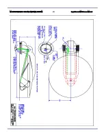
horizontal. (Note: The feed boom tubes are indicated on the interface drawing and are
parallel to the antenna boresight.) If not, refer to RCI 3000/3050 Controller manual for elevation
zero voltage setting.


