background image

Using the IDL 

Page | 30 

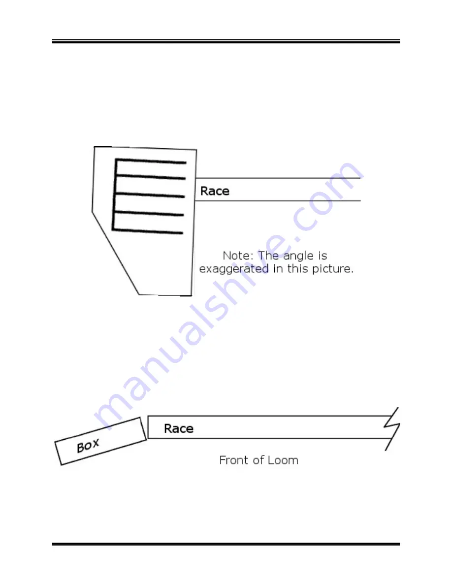
Backplate Tilt 

The shuttle boxes on both sides should
relative to the

 shuttle race. This angle will cause the shut

race as it travels across.  
If the boxes are misaligned in the opposite

an errant trajectory and may 
unsafe condition. 

Backplate Cant 

Both shuttle box assemblies must also carry a slight angle

In the same way that a bit of downward angle causes the shuttle
the race, a slight canting of the backplates will

located against the reed as it travels across
If the backplate is angled too 

of the

 reed and exit the loom

forward, the shuttle will speed off the race.

Shuttle Box to

 Race Alignment

There are two critical alignments to consider


Industrial Dobby Loom User's Manual


The shuttle boxes on both sides should carry a very slight downward angle 

shuttle race. This angle will cause the shuttle to “hug” the 


the boxes are misaligned in the opposite direction, the shuttle will take on 

an errant trajectory and may launch off the race — obviously creating an 

lies must also carry a slight angle towards the reed

the same way that a bit of downward angle causes the shuttle

the race, a slight canting of the backplates will keep

 the shuttle properly 

located against the reed as it travels across the

 loom.  

oo far back, it will cause the shuttle to bounce off 

reed and exit the loom area. If the backplate is angled too far 

forward, the shuttle will speed off the race. 

Alignment 

cal alignments to consider here: 

l Dobby Loom User's Manual 


Adjustments 

slight downward angle 

tle to “hug” the 

direction, the shuttle will take on 

obviously creating an 


towards the reed.


the same way that a bit of downward angle causes the shuttle to stick to 

the shuttle properly 

will cause the shuttle to bounce off 

If the backplate is angled too far 


Summary of Contents for Industrial Dobby Loom

Page 1: ...Industrial Dobby Loom User s Manual AVL Looms 2360 Park Ave Chico CA 95928 8305 U S A 530 893 4915 530 893 1372 fax info avlusa com www avlusa com Copyright 2018 All Rights Reserved Worldwide ...

Page 2: ......

Page 3: ...he Loom 10 Flexible Air Link 11 Floor Brackets 11 Power Supply 11 Setup Your Computer 11 Setup the Air System 12 Compressor 12 Filter Regulator FR 12 Regulators 13 Cylinder Flow Controls Speed Controls 14 Testing The Loom 14 Pre Operation Checklist 15 Normal Loom Firing Sequence 15 Using the IDL 17 Operating the Loom 18 Manual Loom Control 18 Automatic Loom Control 19 Reversing Cloth Direction 19 ...

Page 4: ...9 Troubleshooting Tip 39 Shuttle Box System 40 Normal Mode 41 Special Mode 43 Extra Mode 44 Maintenance 47 Maintenance 48 General 48 Square and Level the Loom 48 Maintenance 49 Trouble shooting 51 Basic Troubleshooting Tips 52 Shuttle Doesn t Fire 52 Shuttle Won t Stay On Race 52 Shuttle Doesn t Box Completely 52 Loom Fires on Empty Box 52 Loom Stops Red Light Is On 52 Loom Stops Green Light Is On...

Page 5: ...Manual Introductory Information Introductory Information Page 5 To make the adjustment 55 Troubleshooting the Picker Cylinders 56 Diagram of the PLC 57 The Fine Print 59 AVL Customer Service 60 AVL Warranty 60 AVL Returns Policy 61 ...

Page 6: ......

Page 7: ...Industrial Dobby Loom User s Manual Introductory Information Introductory Information Page 1 INTRODUCTORY INFORMATION INTRODUCTORY INFORMATION ...

Page 8: ...FACTURING IF THE EQUIPMENT IS USED IN A MANNER NOT SPECIFIED BY THE MANUFACTURER THE PROTECTION PROVIDED BY THE EQUIPMENT MAY BE IMPAIRED WARNING ELECTRICAL SHOCK HAZARD DO NOT TAMPER WITH ELECTRICAL WIRES OR OPERATE THE LOOM WITH SAFETY PANELS OPENED OR REMOVED WARNING PINCH CRUSH AND FINGER CUT OFF HAZARDS DO NOT OPERATE THE LOOM WITH SAFETY PANELS OPENED OR REMOVED DO NOT PLACE HANDS IN MOVING ...

Page 9: ...STOPS OR ON OFF BREAKER SWITCHES WARNING USE OF CONDUCTIVE FIBER OR YARN ON OR AROUND THIS EQUIPMENT WILL VOID WARRANTY AND MAY DAMAGE EQUIPMENT WARNING THIS EQUIPMENT IS CLASSIFIED FOR LIGHT INDUSTRIAL ENVIRONMENT ONLY OPERATION OF HIGH CURRENT DRAW EQUIPMENT EX MIG WELDER ON THE SAME ELECTRICAL CIRCUITS MAY CAUSE EQUIPMENT FAILURE Safety Features Covers and shielding separate weaver from moving ...

Page 10: ......

Page 11: ...Industrial Dobby Loom User s Manual IDL Setup IDL Setup Page 5 IDL SETUP IDL SETUP ...

Page 12: ...rmation you need to know like how to start the IDL how to make adjustments and what you ll need to do to keep your loom in top working condition We have provided detailed steps to follow and illustrations to guide you You will also find a Maintenance and Troubleshooting section in the back of the manual PREPARATIONS Your IDL will have been assembled and tested before it left the factory An AVL tec...

Page 13: ...e particularly careful about your hands 4 Disconnect both electrical power and air before you do any maintenance on your loom 5 Don t guess If you re unsure about anything and this manual doesn t help call our technical support number at 800 626 9615 6 Never stand at the end of the shuttle boxes when the loom is in motion BE SAFE You ll come across other safety tips as you read more about your IDL...

Page 14: ...he loom when weaving In an emergency where the loom needs to be stopped immediately you should use the Emergency Stop However anything that has already been placed in motion will complete that motion For instance if the shuttle has been thrown it will not stop until it hits something 1 There are three ways to stop your loom a Press STOP b Press PAUSE c Press EMERGENCY STOP Figure 1 Control Panel E...

Page 15: ...om on and press RUN The loom resets to the beginning of the next cycle This may result in a flaw in the fabric if it is not accounted for Restarting After an Emergency Stop If you ve used this mode your loom will have stopped somewhere mid cycle that is anywhere between a cloth advance and a beater return However when you re start the loom it will re set automatically to the beginning of the next ...

Page 16: ... becomes a part of your regular loom maintenance 1 Using a tape measure note these measurements a The distance from the inside corner of the rear left vertical to the inside corner of the front right vertical b The distance from the inside corner of the rear right vertical to the inside corner of the front left vertical 2 These two measurements should match If they do not you will need to adjust t...

Page 17: ...e anchored to the floor Brackets made for this purpose are available from AVL If you opt to bolt your loom to the floor be sure to first check that it is square Bolting the loom to the floor will over time reduce the need to adjust the loom for square It will also reduce the need to make adjustments to the flyshuttle boxes Power Supply AVL strongly recommends that you use a surge protector and an ...

Page 18: ...tem YSTEM compressor must be able to deliver a minimum of 25 cubic pounds per square inch Regulator is mounted on the back of the Computer This is where the air line coming from the compressor connects to the loom The primary function of this device is to control the air pressure coming into Air pressure is measured in pounds per square inch P S I If you re not r with pneumatic systems just think ...

Page 19: ...he air that is delivered to the different loom systems These are located on the component board in the computer cabinet in the Component box to the left of the FR Each regulator has a gauge labeled with the name Figure 3 Regulators ntrol power FLOW CONTROLS discussed below control the speed at which your systems operate Each regulator controls one system and is labeled on the air board computer ca...

Page 20: ...ders Cloth Storage Cloth Storage Cylinder These different systems will operate according to the choreography which you establish You ll want the loom to lift beat and pick according to your weaving needs at a particular moment This means you ll need to set the controls for each of the systems It soundsmuch more complicated than it really is and once you ve made your initial setting you won t need ...

Page 21: ...fore you put the loom in motion Check that the shuttle boxes align with the shuttle race Check that the shuttle boxes traverse their support rods without rubbing or binding move up and down by hand Check that the air line is connected Check that the power cord is connected Check that the Compu Dobby is connected Check that the FR and system regulators are at the expected settings NORMAL LOOM FIRIN...

Page 22: ......

Page 23: ...Industrial Dobby Loom User s Manual Using the IDL Using the IDL Page 17 USING THE IDL USING THE IDL ...

Page 24: ...ontrol box to MANUAL 3 Load your shuttles into the shuttleboxes pushing them all the way against the picker To test the loom load an empty shuttle into box 2 4 At the Control box turn the TURN ON PUSH OFF button clockwise The loom is now operational 5 Using the hand control that connects to the Control box depress the ADVANCE button once the Cloth Beam rotates a degree or so 6 Depress the DOBBY bu...

Page 25: ...o AUTO the red light on is CAUTION The next step will put the loom in motion Be sure that no one is standing at either end of the shuttle race and that all hands are clear of the front of the beater and other pinch points 2 When you re ready press the green RUN button the green light is on the red light is off the loom will run through the weaving cycle continuously 3 Hit the PAUSE button at any t...

Page 26: ...th Direction 2 Lift the Tension Weight Arm to release tension on the warp You ll want to use a piece of cord to secure the arm to the Upper horizontal on the loom frame 3 Pull the pin at the Cloth Storage beam to disconnect it from the drive hub Figure 4 Cloth Storage Pin ...

Page 27: ...ustrial Dobby Loom User s Manual Remove the spacer clip from the Automatic Advance drive Figure 5 Auto Advance Engaged Disengage the Automatic Advance gear by pushing the axle end toward the center of the loom until the gears are unmeshed and large washer touches the small bearing housing Install clip between the large bearing housing and the gear Figure 6 Auto Advance Disengaged warp Move the Spa...

Page 28: ...that must be adhered to for your IDL to function properly Synchronized Loom Motion There is a particular order in which you ll want to adjust each of the loom s mechanisms When you ve finished all the systems will work smoothly and in concert We recommend that you proceed as follows 1 Automatic Cloth Advance 2 Dobby 3 Beater 4 Box Changing 5 Automatic Cloth Storage Automatic Cloth Advance Speed Ad...

Page 29: ...oosen the two bolts holding the left Fafnir Industrial Dobby Loom User s Manual Use a small screwdriver to turn each screw in or out the screws counterclockwise to accelerate and clockwise to retard the action of the Automatic Cloth Advance 7 Automatic Advance Cylinder and Cloth Beam Gear Adjustment adjust the Automatic Advance and Cloth Beam Gear Mesh Loosen the two bolts holding the left Fafnir ...

Page 30: ...olling the cloth beam toward you feed a single piece of paper between the small Automatic Advance gear and the larger cloth beam gear stopping when the paper is trapped between the gears 3 Push down on the Cloth beam to seat the gears into the paper Figure 9 Cloth Beam Gears 4 Retighten the VCJT1 bearing ...

Page 31: ...e harnesses are raised and lowered is controlled from the Dobby Cylinder This is the large air cylinder that extends from the bottom of the dobby head on the right side of the loom You set the flow controls on this cylinder in exactly the same way that you adjust those on the Automatic Advance Cylinder Remember Clockwise retards counterclockwise speeds 1 Find the cylinder on the right side of the ...

Page 32: ...nd clockwise to retard the action of the Dobby Cylinder Dobby Cylinder Speed Adjustment The action of the harnesses needs to be coordinated with the action of the Adjustment The shuttle boxes were adjusted when the loom was first installed at your over time they may require some attention You ll time to check these adjustments if your usually tame shuttle seems enly to have become an unguided miss...

Page 33: ...tle box to race alignment To adjust the shuttle boxes you will use the bolts attaching the backplate to the side frame first Once you have the backplate at the right height you can make minute adjustments to the shuttleboxes by sliding them up or down 1 Loosen the three bolts on the back that attach the backplate to the metal bracket ...

Page 34: ...Using the IDL Industrial Dobby Loom User s Manual Page 28 Adjustments 2 Adjust the backplate to the correct angle and position 3 Tighten the bolts ...

Page 35: ...29 4 Loosen the stop collar securing the shuttleboxes on the rail 5 Nudge the shuttleboxes up or down on the front rails to complete your adjustment Note Make sure the cylinders can travel completely to the end of their motion plus a small gap 6 Tighten the stop collar ...

Page 36: ...angle shuttle race This angle will cause the shuttle to hug the the boxes are misaligned in the opposite direction the shuttle will take on an errant trajectory and may launch off the race obviously creating an lies must also carry a slight angle towards the reed the same way that a bit of downward angle causes the shuttle the race a slight canting of the backplates will keep the shuttle properly ...

Page 37: ...ly will be adjusted at a very slight to no angle so it s only the immediately opposite the end of the race which concerns This edge should be at the same height as the top of the the shuttle can make a smooth entry into the Shuttle box either lower or higher than the race you ll loosen the bolts in the large box mounting bracket that attaches the Shuttle box Assembly to the side of theloom This wi...

Page 38: ...ssembly will be subjected to constant jarring and possible damage Because the action of the boxes needs to be synchronous keep the up down box speed equal 1 Find the cylinder at the bottom of the flyshuttle boxes You ll see that there are two plastic air tubes coming into the cylinder 2 At both connecting points there is an adjusting screw These are the flow controls 3 Use a small screwdriver to t...

Page 39: ...e screws counterclockwise to accelerate and clock speed of the shuttleboxes Control power not speed The only thing you need concerned about here is that the action of the Cloth Storage Cylinder greater than that of the Automatic Advance Cylinder directly above it Storage Cylinder is set to overpower the Advance Cylinder it will cause the prevent this set the regulator gauge at about storage mechan...

Page 40: ...ve the rod end up or down in the slot When you move the rod end up the Cloth beam rotates more and you have fewer picks per inch Your IDL is provided with four Automatic Advance sleeves Each of these will cover a different pick range The smaller the sleeve the fewer picks per inch There are two ways to adjust your pick count 1 By increasing or decreasing the stroke of the adjusting lever Move the ...

Page 41: ... 5 16 Top 4 Middle 5 Bottom 7 2 1 13 16 Top 6 Middle 9 Bottom 14 3 2 5 16 Top 16 Middle 20 Bottom 30 4 2 9 16 Top 25 Middle 40 Bottom 60 These pick counts are approximations and are related to warp tension and by how hard the weft is beat into the warp Increasing the warp tension and how hard you beat can increase the pick count ...

Page 42: ...oth Storage system So you can cut off your work at any time without losing warp tension To start 1 Pull the warp approximately 10 beyond the Cloth beam 2 Push the Pressure Roller into the warp under the Cloth beam until it snaps into place 3 To remove the roller relieve tension two knobs in front under the Cloth beam push the arm and remove the roller ...

Page 43: ...Industrial Dobby Loom User s Manual em To Prevent Draw In TO PREVENT DRAW IN System is used to maintain a good selvage and prevent You need to weave a few inches so you have enough selvage to work with two rollers barrels working in tandem which grab the selvage prevent it from drawing in This device looks complicated but is in fact relatively easy to work Refer to the accompanying illustration an...

Page 44: ...hings like the choice of rings and the length of the needles However we can offer some useful guidelines to help get you started We provide you with a set of general purpose rings If the needles are holding the selvage sufficiently well and isn t causing looping or leaving a perforated line in the warp you re doing fine If however you re having problems you made need to investigate different rings...

Page 45: ...tly the tension you want Most weavers find that they can weave with less tension using this system If you ve laid on a very heavy warp you may need to add weight to the arm Additional weights can be obtained from AVL Conversely warps comprised of extremely fine yarns may require a lighter weight AVL can provide you with a half weight if you so desire To make it a little easier to learn we ve creat...

Page 46: ...ossible umstances should you apply a wax or finish or otherwise treat the cable race on the drum YSTEM When you click on the Shuttle box System in the Weave Menu the box System Window opens Choose the Shuttle Box Mode that is appropriate for your Modes one to four shuttles up to six shuttles designed for Tartan weaving There must be an even number of picks of each color seven shuttle weaving When ...

Page 47: ...g and is the simplest Shuttles move from box 1 on one side to box 1 on the other side to box 2 from box 3 to box 3 and from box 4 to box 4 The Shuttle boxes on both sides move up and down together While any of the indexed colors can be used it is usually simplest to first five indexed colors 0 4 to indicate the color usage in the pattern draft change the color associated with any index Number to w...

Page 48: ...ht and 3 left This helps keep the threads from catching on each other especially good for pick and pick weaving i e shadow weave or Summer and Winter Index Shuttle Box 0 2 Right or Left 1 1 Right 2 2 Right 3 3 Left 4 4 Left If you are using three or four colors and shuttles place the shuttles as indicated in the table In NORMAL mode your design can have any number of picks of any color in any orde...

Page 49: ... especially for weaving Tartans six shuttles The following table shows which index Numbers and how to arrange thecolors in the shuttle boxes order for this mode to work correctly each shuttle must throw two picks in a Shuttle Box 1 Left 1 Right 2 Left 2 Right 4 Left 4 Right that Shuttle box 3 remains open on both sides These boxes are left open to accept any of the six shuttles from either side on...

Page 50: ...mber of ends and t majority of Tartan setts use six or fewer colors Many for these it is possible to use the NORMAL mode setts calling for more than six colors it is possible to use the optional STOP feature to stop the loom switch to Manual operation throw a by hand and then go back to the Automatic is the most complicated mode and is used for weaving with shuttles Both sets of shuttle boxes move...

Page 51: ...moves to the open space on the right The fourth color moves from right to left At the fifth color change we see that there is not an open box to accept the aqua shuttle It is necessary to either change the color rotation or try a different starting arrangement and start again at step 1 Continue moving the colors from side to side rearranging or editing as needed Go through the full repeat several ...

Page 52: ...dex 0 1 1 Index 1 1 2 Index 2 1 3 Index 3 1 4 Index 4 2 1 Index 5 2 2 Index 6 2 3 Index 7 2 4 Index 8 3 1 Index 9 3 2 Index 10 3 3 Index 11 3 4 Index 12 4 1 Index 13 4 2 Index 14 4 3 Index 15 4 4 After the initial movements the on board central processing unit keeps track of where each shuttle is and launches the one called for in the weft color grid as the weaving progresses 12 4 4 15 11 3 3 10 6...

Page 53: ...Industrial Dobby Loom User s Manual Maintenance Maintenance Page 47 MAINTENANCE MAINTENANCE ...

Page 54: ...t the same time this system will shut the loom down the shed will open slightly and the loom will abruptly turn off Air Quality Poor air quality will produce a number of problems This can t be stressed enough Dirt oil and moisture in your air delivery system can clog and erode valves and other air components Affected valves may operate sluggishly or not operate at all Always use a clean air source...

Page 55: ...eaving environment requires that you do these things more or less often DAILY Clean any lint away from the optical eyes and the Compu Dobby WEEKLY Check the oil level in the lubricator Clean the Compu Dobby filter soap and water air dry Check the loom frame bolts for tightness MONTHLY Lubricate the Shuttle Box Spring with Teflon spray or silicone TRI FLOW for example Clean and grease zerk fitting ...

Page 56: ......

Page 57: ...Industrial Dobby Loom User s Manual Trouble shooting Troubleshooting Page 51 TROUBLE SHOOTING TROUBLESHOOTING ...

Page 58: ...e may have been placed in the wrong box A drafting error may have been made check the program Shuttle Won t Stay On Race The bobbin is improperly wound A knot in the weft is catching on the shuttle tensioner The Bobbin is nearly empty and out of balance The Shuttle boxes need to be adjusted Shuttle Doesn t Box Completely Insufficient air pressure The binder shuttle brake is too tight The shuttle b...

Page 59: ... to make one adjustment This adjustment is made at the front of the Dobby head This is the critical adjustment Without this your Compu Dobby won t work There are two retention brackets that hold the Compu Dobby unit into the Dobby Head The set screws in the middle of these brackets are your adjusting points Your goal is to locate the Compu Dobby unit so that when each solenoid is extended it pushe...

Page 60: ...m and use the hand control to activate the dobby You should hear the solenoids activate they make an abrupt snapping sound If this doesn t happen repeat your treadling 5 Return to the Compu Dobby unit and peering in from the bottom verify that the two solenoids are extended 6 Pull back on the Compu Dobby unit so that it rests against the adjustment brackets 7 Now use the 1 8 Allen wrench to turn t...

Page 61: ...4 twill or a 2 2 twill so you can treadle through and see each shaft lift ADJUSTING THE SHUTTLE SENSORS Symptom the picker is firing when there is no shuttle in the box Remember ALL ADJUSTMENTS AND OBSERVATIONS MUST BE MADE WHILE LOOM IS ON AND IN THE MANUAL MODE Adjust the shuttle sensors in the PLC when the shuttle is in the right box 12 will light and 13 for the left side box You need to check ...

Page 62: ...n the box and seeing if the light turns green 4 Carefully retighten the bolts TROUBLESHOOTING THE PICKER CYLINDERS 1 With the loom turned off move the Picker Arm back and forth checking for any pressure that might result in binding and hampering the movement of the Arm including the Picker Slot the Picker at the Shuttle Shelf the hardware mounts for the Arm to the Picker and Arm Pivot ...

Page 63: ...Industrial Dobby Loom User s Manual Diagram of the PLC DIAGRAM OF THE PLC Industrial Dobby Loom User s Manual Trouble PLC Trouble shooting Page 57 ...

Page 64: ......

Page 65: ...Industrial Dobby Loom User s Manual The Fine Print The Fine Print Page 59 THE FINE PRINT THE FINE PRINT ...

Page 66: ...erform according to AVL s specifications Any repair during the Original Warranty Period will be carried out without charge to you for parts except applicable taxes if any You will be responsible for all labor in connection with installation of the parts and service upon the Product as well as the cost of shipping involved New Accessories Loom Upgrade Parts and Replacement Parts Subject to the limi...

Page 67: ... Digital Assistant or a Personal Computer which are manufactured by a third party ies and which may be under warranty through the original manufacturer AVL is not responsible for any warranty coverage that may be offered concerning these products and you must contact those manufacturers directly regarding any available warranty coverage The performance or functionality of any software that is sold...

Reviews: