background image

OVATION PH 8.3

5

Getti ng star ted

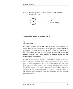
Abb. 5. Pin assignment of the supply socket for AVM 

turntables (14)

1.4 Installation of input cards

ℹ 

CAUTION

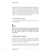
Keep  the  unit  switched  off  until  all  audio  connections  are
made.  Please  make  sure  the  mains  plug  is  removed  before
you  open  the  unit.  Input  cards  may  never  be  installed  or
removed  while  the  unit  is  powered  on.  In  case  of  any  doubt,
please  consult  your  local  dealer  to  assist  you  with  the
assembly of input cards.

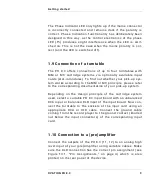
The  PH  8.3  is  equipped  with  a  total  of  four  slots  on  its  rear
side  and  can  be  fitted  with  optionally  available  input  cards
(slot-in  modules).  These  slots  are  counted  from  the  left  side
(see  Figure 2,  “Rear  panel,”  on  page 3).  Existing  input  cards
can  be arranged  in  any order. The  dimensions  of  the  different
input cards are identical (width of the cover plate, position of
the  connectors).  Unused  slots  are  covered  with  a  dummy
plate supplied.

1) 15V 
2) Ground (GND)

Summary of Contents for OVATION PH 8.3

Page 1: ...OVATION PH 8 3 Operating instructions AUDIOPHILE MEISTERSTÜCKE SEIT 1986 ...

Page 2: ...ith confirm that the unit to which this manual belongs fulfills the EC rules necessary to obtain the sign the necessary measurements were taken with positive results AVM Audio Video Manufaktur GmbH Daimlerstraße 8 76316 Malsch Germany www avm audio ...

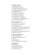
Page 3: ...rntable supply 10 2 Basic operation 11 2 1 First operation self test 11 2 2 Switching on standby 11 2 3 Input selection 12 2 4 Adjustment of the cartridge system 12 2 5 Selection of a suitable input card 13 2 6 Gain adjustment 14 2 7 Selection of an equalization curve 15 2 8 Subsonic Filter 16 3 Advanced Settings 18 3 1 Personal Setup 18 3 2 Reset Factory settings 20 3 3 Info 20 3 4 Demo Mode 21 3...

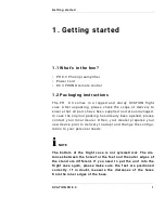
Page 4: ... case the original packing has already been opened please contact your local dealer Often your dealer prepares your new device prior to delivery to adapt and change the configu ration to your personal needs ℹ NOTE The bottom of the flight case is not symmetrical The dis tances between the holes for the feet and the outer edges of the stand are different If you need to put the unit into the flight ...

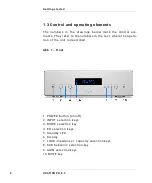
Page 5: ... ele ments They refer to the numbers in the text where the opera tion of the unit is described Abb 1 Front 1 POWER button on off 2 INPUT selection keys 3 MODE selection key 4 EQ selection keys 5 Standby LED 6 Display 7 LOAD impedance capacity selection keys 8 SUB Subsonic selection key 9 GAIN selection keys 10 MUTE key ...

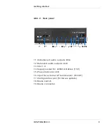
Page 6: ...1 Unbalanced audio outputs RCA 12 Balanced audio outputs XLR 13 Slot 1 4 14 Supply socket for AVM turntables 15V 15 Phase Indicator LED 16 Input for external infrared sensor IR EXT 17 Configuration port firmware update 18 Mains switch 19 Mains connector ...

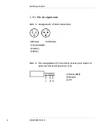
Page 7: ... PH 8 3 1 3 1 Pin Assignments Abb 3 Assignment of XLR connectors Abb 4 Pin assignment of the 3 5mm stereo jack input for external infrared receivers 16 XLR Input XLR Output 1 Ground GND 2 POS 3 NEG c Ground GND d IR signal e 5V ...

Page 8: ...In case of any doubt please consult your local dealer to assist you with the assembly of input cards The PH 8 3 is equipped with a total of four slots on its rear side and can be fitted with optionally available input cards slot in modules These slots are counted from the left side see Figure 2 Rear panel on page 3 Existing input cards can be arranged in any order The dimensions of the different i...

Page 9: ...ards for the PH 8 3 are offered the inter nal operating software firmware may need an update The corresponding software is stored on a small data carrier a so called EEPROM dongle If necessary this will be supplied with the purchase of a new input card To perform an update switch off the device with the mains switch 18 and insert the EEPROM dongle into the configura tion port 17 The contacts of th...

Page 10: ...are is now installed a second time During this process about one minute the display 6 remains dark and the standby LED 5 flashes When the pro cess is complete you will be asked to switch off the mains voltage mains switch 18 and remove the EEPROM Dongle The unit can then be switched on again and is ready for opera tion 1 6 Installation and cooling The unit may become hot depending on demanded outp...

Page 11: ...1 7 Connection to mains Connect the supplied power cord to the mains connector 27 and a wall outlet ℹ NOTE Keep the unit switched off until all audio connections are made If the unit is still cold after unpacking or from trans port leave it in your listening room for about one hour with out mains power so that it can adjust to the room temperature 1 8 Mains phase indicator Phono amplifiers are by ...

Page 12: ...tem works according to the MM or MC principle please refer to the corresponding documentation of your pick up system Depending on the design principle of the cartridge system used select a suitable PH 8 3 input board with an unbalanced RCA input or balanced XLR input of the input board Now con nect the turntable to the sockets of the input card using an appropriate RCA or XLR cable Connect the gro...

Page 13: ... rest of the power supply unit of the PH 8 3 and has an elaborately filtered output replaces the stan dard power supply unit supplied with your AVM turntable In this case use the supply socket for AVM turntables 15 on the rear panel Your specialist dealer will be pleased to supply you with an appropriate cable 1 11 1 External infrared input If you have installed your PH 8 3 in such a way that the ...

Page 14: ...rent status of the hardware test is shown on the display 6 Upon successful completion of the hardware test the device switches to standby mode This process may take a few seconds 2 2 Switching on standby Using the power button 1 you can switch between on ope rate and standby When switched on the display 6 lights up and the LED 3 is switched off In standby mode the display is switched off and the L...

Page 15: ...device is not completely disconnected from the mains To disconnect completely use the mains switch 18 on the back of the unit or unplug the power cord from the mains connector 19 2 3 Input selection Select the desired input card with the INPUT selection keys 2 The currently selected input card is indicated on the dis play 6 2 4 Adjustment of the cartridge system For optimal sound reproduction the ...

Page 16: ...ridge system must be operated with the appropriate terminating impedance or capacity This is particularly important for MM systems as the terminating capacity generates a high fre quency resonance that extends the frequency response If the capacity is too low the sound of the pick up system may lack brilliance If the capacity is too high the resonance shifts too far down and thus causes strong pea...

Page 17: ...increased by the capacity of the cable by about 100 pF We recommend to select a setting on the PH 8 3 that is about 100 pF below the manufacturer s recommended capacity It is worth experimenting to find out the setting for optimum sound quality Wrong settings will not harm the cartridge or the PH 8 3 2 4 3 Gain adjustment The output voltage of cartridges is not standardized There fore there are ve...

Page 18: ...signal is pre equalized during the production process In the bass range the level is lowered in the high frequency range the level is raised Since this is a linear distortion that does not produce any harmonics this pre equalization process can be compensated when the record is played by applying an inver ted equalization curve to the actual pressing curve Before the so called RIAA equalization be...

Page 19: ...h the played back music signal but is caused by wavy records or turntables that are sensitive to footfall sound To suppress such noises the PH 8 3 is provided with a highly effective subsonic filter which suppresses all signals below 30 Hz with a steep slope For activation deactivation use the Subsonic selection key SUB 8 The PH 8 3 stores the subsonic filter setting for each individual card and r...

Page 20: ...ral times to phase rotation by 180 in STEREO display stereo or MONO mono For playback of older mono records the setting of the PH 8 3 to MONO can be very helpful as the groove noise present in stereo is suppressed to a certain degree If in addition a record has been recorded out of phase the PH 8 3 can easily correct this In this case choose one of the following set tings stereo or mono ...

Page 21: ...by mode Now press and hold the ope rating MODE selection key 3 and switch on the PH 8 3 with the POWER button on the front 1 The display 6 now shows the Personal Setup menu Individual menu items can be selec ted with both EQ selection keys 4 available options can be adjusted to your requirements with the selection LOAD selec tion keys 9 If you wish to exit the setup press the MUTE key 10 The selec...

Page 22: ...er function is used the unit automatically switches to standby mode Of course the unit can be swit ched on again at any time by pressing the POWER key 1 Depending on the selected setting ON or OFF the automa tic switch off is activated or deactivated NOTE Please note that deactivating the automatic standby function leads to increased power consumption as the device remains in operation even if no ...

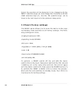
Page 23: ...nd thus to all factory settings The follo wing settings are reset Display brightness 100 Operating mode STEREO EQ curve RIAA Impedance 1 kOhm MC 100 pF MM Gain 0 dB Input name STANDARD NAME Auto Standby ON To perform a RESET switch off the unit with the mains switch 18 on the back Now press and hold the EQ 4 and LOAD key 7 at the same time and turn the unit on again with the mains switch 18 Now pr...

Page 24: ...y mode 3 4 Demo Mode The PH 8 3 provies a so called Demo Mode This mode is pri marily intended for specialist dealers to show the respective features of the device as a continous slide show on the dis play 6 during a presentation at a retail store or an exhibi tion To activate the Demo Mode switch off the device using the mains switch 18 Now press and hold the MUTE button 10 while you switch on th...

Page 25: ...PHONO remote control Abb 4 Control elements of the RC 3 PHONO The PH 8 3 is supplied with the RC 3 PHONO remote control The keys on the RC 3 PHONO remote control correspond to the keys on the front panel of the unit and have the same functionality ...

Page 26: ...e range of the remote control decreases significantly new batteries must be installed Remove the six screws on the bottom marked with arrows Now turn the remote control over and take out the bottom with the printed circuit board Remove the used batteries and replace them with two new ones of the same type Lithium button cell 3V type CR2032 When inserting the batteries make sure that the polarity o...

Page 27: ... with a damp cloth Do not use any solvents or abrasive cleaners as these could damage the surface or print 4 2 Troubleshooting Often supposed defects can be traced back to inadvertent operating errors Occasionally other components connected to the device are also responsible for a malfunction There fore before you contact your dealer or AVM about a defect we would like to ask you to rule out the f...

Page 28: ...ase contact your specialist dealer 4 2 2 Hum during music playback a A turntable is located near an electrical device e g power amplifier whose stray magnetic field scatters into the car tridge system or cable b The ground cable of the record player is not connected Connect the earth cable coming from the record player to the earth contact knurled nut below the input sockets of the relevant plug i...

Page 29: ...ty are 1 The unit must have been purchased from an authorised dealer Equipment from other sources will not be repaired not even at charge 2 The warranty registration is done via our website www avm audio 3 The fault must not have been caused by improper handling or intervention in the device 4 In case of repair the device must be sent to us free of charge in its original packaging If this is not t...

Page 30: ...charge a handling fee PLEASE NOTE If you are not shipping your device from Germany please makre sure you have the correct export or import documents Unfortunately we cannot assume any costs arising from improper export failure to declare or customs clearance 4 4 Specifications 4 4 1 Base unit Settings Sub filter switchable 30 Hz 12 dB Octave Sensitivity adjustable 10 5 0 5 10 dB MONO STERO Switcha...

Page 31: ...cht 1592µs 318µs 57µs NOTE All equalization curves for LPs 33 1 3 U min Outputs Output impedance RCA 50 Ohm Output impedance XLR 100 Ohm Max Output voltage RCA 7 V Max Output voltage XLR 14 V Power supply turntable 15V 1 5 A galvanically isolated Miscellaneous Mains voltage 100 240VAC 50 60 Hz Power consumption max 25W Power consumption standby mode stand by 0 45W Power consumption Power switch 18...

Page 32: ...r Silver Chrome 791511837079 791511837055 Black Black Chrome 791511837062 791511837048 4 4 3 Plug in cards MC RCA MC XLR Sensitivity 1 kHz Ua 1V 55 100 170 315 550 µV adjustable Overload 1 kHz 0dB 2 5 mV Impedance 1000 500 300 100 50 30 Ohm einstellbar S N 0 5mV 0dB 33 Ohm 73 dB 77 dB A MM RCA Sensitivity 1 kHz Ua 1V 0 5 0 9 1 6 2 8 5 mV ein stellbar Overload 1 kHz 0dB 25 mV Impedance 50 100 150 2...

Reviews: