89
User Manual
15
Operating Requirements
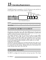
The EKP-IV must be connected to a 10–35 V DC power source and the an-
tenna requires a clear view of the sky in order to operate.
Fig. 15 - Power and I/O Connector
NOTE
The cable that ends with wires is available as an optional part. Please contact your local C-MAP
office for details.
15.1 ANTENNA ASSEMBLY & PLACEMENT
The antenna comes with a 5 meter cable with a SMB connector. The antenna is
designed for use inside the aircraft. It can be temporarily mounted on the
aircraft’s dashboard using the included velcro strip.
The antenna must have a clear view of the sky in order to receive satellite
signals. GPS uses “line of sight” signals to locate and track satellites. If the
signals are obstructed by dense objects such as aluminum, steel or even heavy
ice, the EKP-IV will not operate properly. Signals may also be blocked by
heated wind screens (fiberglass, plexiglass and other plastics are nor-mally
transparent to GPS signals).
The antenna can be mounted to any convenient surface that has a clear view of
the sky. If you find that the EKP-IV does not locate and track satellites quickly
or consistently, move the antenna. Moving the location of the antenna a few
inches often provides a better view of the sky.
15.2 SECURING THE EKP-IV
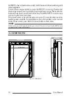
The EKP-IV was designed to be mounted on your leg for operation. This will put
Summary of Contents for EKP IV
Page 1: ...User Manual Via Caboto 9 54036 Marina di Carrara MS ITALIA E mail info avmap it ...
Page 4: ...6 User Manual ...
Page 36: ...38 User Manual ...
Page 40: ...42 User Manual ...
Page 48: ...50 User Manual ...
Page 58: ...60 User Manual ...
Page 62: ...64 User Manual ...


