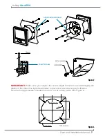
User and Installation Manual -
9
AvMap
Ultra EFIS
Connect the Pitot line to the port labeled
PITOT and the static line to the port labeled
STATIC.
IMPORTANT
:
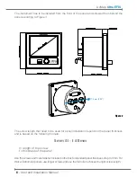
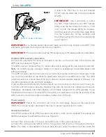
Use 2 wrenches to screw
the NPT male fitting into the NPT female
fitting. Use the first wrench (14mm or 9/16
inch) to hold the female fitting on its place,
and the second key to screw the male fitting
into the female one. Screw carefully until
the fittings get tight but avoid overtightening
(see Figure 7).
IMPORTANT
:
Use flexible plastic tubes and make sure the tubes fit tight on the NPT Pitot
and static ports and can not get loose due to vibration.
IMPORTANT
: We recommend to test the Pitot-static system for leakage after any alteration.
External GPS receiver connection
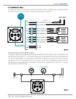
Connect the external GPS receiver, included in the box, on the back side of the Ultra to the
GPS port as shown on
Figure 5.
The GPS receiver comes with a 1,5 meter cable and is designed for use inside the aircraft.
Note:
an additional gps extension cable of 2 meter is available at the AvMap dealer and
AvMap webshop.
The GPS receiver can be mounted to any convenient surface that has a clear view of the
sky. It can be mounted on the aircraft’s dashboard using the included Velcro strip. The GPS
receiver must have a clear view of the sky in order to receive satellite signals. GPS uses “line
of sight” signals to locate and track satellites.
If the signals are obstructed by dense objects such as aluminum, steel or even heavy ice,
the Ultra will not operate properly. Signals may also be blocked by heated wind screens
(fibreglass, plexiglass and other plastics are normally transparent to GPS signals). If you
find that the Ultra does not locate GPS FIX quickly or consistently, moving the location of the
GPS receiver a few inches often provides a better view of the sky.
Power supply
IMPORTANT
: Power the Ultra from an 10 to 35 Vdc supply. Mount on the power wire
(RED) the 1A fuse holder, provided in the box, to protect against short circuits.
Serial Connection
Ultra EFIS comes with two RS232 serial connections, both can be enabled for sending out
NMEA messages to external devices (see Figure 5):
Connect the Ultra serial TX wire to serial RX wire of the external device.
Connect the Ultra ground (GND) wire to the ground (GND) wire of the external device.
Note:
The Ultra is not enabled to receive data through serial, therefore the Ultra serial RX
Wrench 1 (14mm or 9/16 inch)
Wrench 2
Figure 7


