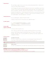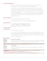
NOTE:
Cable sets without audio cables are available
if you do not require speaker and microphone support.
Powering your system
Locate the power cord that came with your switch.
Plug one end into the IEC power connector on the
SwitchView SC4 UAD switch. Ensure the power
switch is off, then plug the other end of the power
cord into an AC wall outlet. Power up your switch
fi rst, then power up all attached servers.
Switching your servers
Press the appropriate front panel button labeled A-D to
access servers in your SwitchView switching system.
Mechanical
H x W x D = 1.75” x 11” x 11” (4.44 x 27.94 x 27.94 cm)
Weight = 4.9 lbs (2.2 kg)
The Power of Being There
®
Quick Installation Guide
SwitchView
®
SC4 UAD
DVI/USB Switch with Audio
The following will help you install your
SwitchView SC4 UAD switch easily.
Should you require further assistance, please
contact Avocent Technical Support.
To install the SwitchView SC4 UAD switch
To Contact Avocent Technical Support CALL (888) 793-8763 VISIT www.avocent.com/support DOWNLOAD www.avocent.com
Avocent, the Avocent logo, The Power of Being There, the Cybex logo and SwitchView are registered trademarks of Avocent Corporation or its affi liates. ©2006 Avocent Corporation. All rights reserved.
590-609-616A
Connecting local peripherals
Power down all servers that will be part of your
SwitchView SC4 UAD switching system. Locate
your USB keyboard, DVI monitor, USB mouse,
speakers and microphone. Plug your DVI monitor
cable into the appropriate CONSOLE port on
the left side of the back of your switch. Plug your
USB keyboard cable and your USB mouse cable
into the keyboard and mouse ports respectively.
Plug your speaker cable and microphone cable
into the corresponding ports.
Connecting your servers
Locate your fi rst cable set consisting of one USB
cable, one DVI cable and two audio cables. The
SwitchView SC4 UAD switching system has four
port sets labeled A-D on the rear of the unit. Plug
the USB cable, the two audio cables (speaker
and microphone) and the DVI cable (monitor)
into the corresponding ports on your server.
Plug the other ends into any of the available server
port sets on your SwitchView SC4 UAD switch.
Repeat this process until all servers are prope
rly
attached to the SwitchView SC4 UAD switch
.
1
2
4
1
Power down all
connected servers.
Connect your
peripherals to the
CONSOLE ports
on the switch.
2
Connect the four
servers to the
switch with the
provided cables.
4
Press the
appropriate front
panel button
labeled A-D to
access servers in
your system.
Environmental
Operating Temperature: 41˚ (5˚C) to 104˚ (40˚C)
Storage Temperature: -4˚ (-20˚C) to 122˚ (50˚C)
Input Power: 60 W; Operating Voltage 100-240 VAC
Power Frequency: 50-60 Hz
Supported Hardware
Server: IBM, Sun, PC/AT, USB and 100% compatibles
Video Modes: VGA, SVGA, XGA, SXGA, UXGA,
WVGA, WSVGA, WXGA, WSXGA, WUXGA,
and
HDTV
Maximum Resolution: 1920 x 1080 @ 60Hz
Peripherals: USB keyboard, USB mouse and
IntelliMouse
(USB
only)
3
Power up
your system.
3
Optional
RF ground
(not required for
safety)


