background image


Revision Date: 5/31/2019 

40 


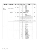
Main Menu 

SubMenu 

Value 

Basic Settings 

Horizontal Pos. 

0 ~ 100 (

50

Vertical Pos. 

0 ~ 100 (

50

OSD Transparency 

0 ~ 4 (

0

OSD Timeout 

5 ~ 60 seconds (

30

OSD Language 

English; 

French; Spanish; German; Dutch; Swedish; 

Portuguese; Danish; Italian 

Splash Screen 

Off; 

Default

; User 

Splash Screen 
Download 

Yes; No 

Power LED 

On

; Off 

RTC & Schedule 

User Mode

; Workday Mode; Everyday Mode 

Adv. Settings 

Smart Switch 

On

; Off 

Presence Detection 

Off; 5 mins; 10 mins; 15 mins; 30 mins, 60 mins; 

120 mins


Wake Up from Sleep 

No; 

Yes

; Never Sleep 

EDID Switch 

1080p; 4K2K@30; 

4K2K@60


Touch Input Mapping 

Auto

; USB Touch 1; USB Touch 2; USB Touch 3 

Game Mode 

On

;


Off


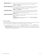
USB Settings 

On

;


Off  

(Touch USB, HID USB, Audio USB, External USB, LAN USB) 

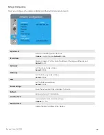
Network Configuration 

Telemetry Interval 

1 ~ 60 seconds (

5

Firmware Update (USB) 

Yes; No 

IoT Firmware Update 

Yes; No 

Restore Factory 
Default 

Yes; No 

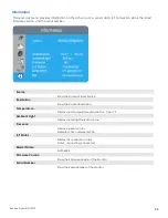
Information 

Source 

Shows the Name of Input Source  

Resolution 

Shows the Current Resolution 

Temperature 

Show the Temperature in °C and °F 

Ambient Light 

Show the Ambient Light in Lux 

Presence 

Show the Presence Detection status (Yes / No) 

IoT Status 

Show the IoT connection status 

Model Name 

AVW-6555 

Firmware Version 

Shows the Firmware Version of the Monitor 

Serial Number 

Shows the Serial Number of the Monitor 


NOTE

      Default settings appear in bold type. 


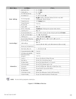
Figure 4-1. OSD Menu Structure


Summary of Contents for AVW-6555

Page 1: ...Revision Date 5 31 2019 AVW 6555 Windows Collaboration Display Model AVW 6555 Installation and OperationManual ...

Page 2: ...served No part of this manual may be reproduced by any mechanical electronic or other means in any form without our prior written permission The trademarks reproduced in this document and used on the products are either owned or licensed by us or by their respective holders You may not reproduce or use the trademarks without our prior written consent COPYRIGHT AND TRADEMARKS ...

Page 3: ... from the outlet immediately Failure to do so may result in fire or electrical shock Contact your dealer for inspection If the display is dropped or the cabinet is damaged remove the power plug from the outlet immediately Failure to do so may result in fire or electrical shock Contact your dealer for inspection To turn off the power of the display press O on the main power switch at side of displa...

Page 4: ...et Don t insert an improper power plug it may cause fire or electric shock Don t place the display on an unstable shelf or surface The display may fall causing injury Please install on a horizontal stable level surface Don t place objects on the display If the display is covered or the vents are blocked the display could overheat and cause a fire If metal or liquid gets into the display it may cau...

Page 5: ...ay If liquid is spilled on the display remove the power and ask qualified service personnel to check the display If the liquid gets on the display s screen please clean it with a dry and soft cloth immediately Don t use any harsh chemical on the display If metal or liquid gets into the display it may cause a fire or an electrical shock Don t install or remove the power plug with wet hands If the d...

Page 6: ...e power plug before cleaning Failure to do so may result in electrical shock or damage Cleaning the surface of the display When the surface of the display becomes dirty please wipe the surface lightly with a soft clean cloth If the surface requires additional cleaning lightly moisten the cloth Do not to let any kind of liquid enter the display as it may cause electrical shock or damage Do not clea...

Page 7: ...ire acts by third parties accidents owner s intentional misuse and fault or use in other improper conditions This product isn t warranted for incidental damages such as profit loss or interruption in business modification or erasure of record data etc caused by use or inability to use of this product This product isn t warranted for any damage caused by inappropriate operation or from not followin...

Page 8: ...suant to part 15 of the FCC Rules These limits are designed to provide reasonable protection against harmful interference when the equipment is operated in a commercial environment This equipment generates uses and can radiate radio frequency energy and if not installed and used in accordance with the instruction manual may cause harmful interference to radio communications Operation of this equip...

Page 9: ...nic equipment By ensuring this product is disposed of correctly you will help prevent potential negative consequences to the environment and human health which could otherwise be caused by inappropriate disposal of this product The recycling of materials will help to conserve natural resources This symbol is only valid in the European Union If you wish to discard this product please contact your l...

Page 10: ...Revision Date 5 31 2019 10 Notes ...

Page 11: ...rts List 17 2 Controls and Functions 18 Display at a Glance 18 Input Panel 22 Remote Control Unit 24 3 Installation 26 Remote Control 26 NotesonBatteries 26 Notes onRemoteControlOperation 26 Quick Setup 27 Installation Considerations 27 Ambient Light 27 Ambient Temperature 27 Ventilation 28 MountingtheDisplay 28 ConnectionstotheDisplay 29 Connecting a Control System or PC 29 ConnectingSourceCompon...

Page 12: ...9 IR Control Code List 59 7 Specifications 60 Supported Timings 61 Overall Dimensions 63 Appendix I Moving and Carrying Notice 66 Moving the Display 66 Carrying the Display 66 Appendix II Installing a Wall Mount 67 Appendix III Installing a NUC VESA Adapter 68 Appendix IV Wall Mount Safety Notes 69 Appendix V Azure IoT Settings 71 Check the IP Address of IoT device 71 Log in to IoT Module 72 Confi...

Page 13: ...OR ENCLOSURE MOUNTING 28 FIGURE 3 2 RS 232 CONTROL SYSTEM CONNECTION 29 FIGURE 3 3 ETHERNET CONNECTION 30 FIGURE 3 4 DISPLAYPORT SOURCE CONNECTION 31 FIGURE 3 5 HDMI SOURCE CONNECTIONS 32 FIGURE 3 6 TYPE C SOURCE CONNECTIONS 33 FIGURE 3 7 TOUCH SCREEN CONTROLLER USB CONNECTION 34 FIGURE 4 1 OSD MENU STRUCTURE 40 FIGURE 7 1 AVW 6555 DISPLAY DIMENSIONS INCH 63 FIGURE 7 2 AVW 6555 DISPLAY DIMENSIONS ...

Page 14: ...Revision Date 5 31 2019 14 Notes ...

Page 15: ...this manual in order to clarify the information and instructions provided Remote and built in keypad button identifiers are set in upper case bold type for example Press EXIT to return to the previous menu Computer input commands you type and output responses that appear on screen is shown in monospace fixed width type for example To change the aspect ratio to Letterbox type 07 00 02 41 53 50 03 0...

Page 16: ...that a given action or omitted action can degrade performance or cause a malfunction WARNING WARNINGS appear when a given action or omitted action can result in damage to the equipment or possible non fatal injury to the user DANGER DANGER appears when a given action can cause severe injury or death Using This Manual Use the following table to locate the specific information you need in this manua...

Page 17: ...ns MIC array Full range stereo speaker module integrated with premium conference camera Compliance with windows 7 8 10 and Mac OS Azure IoT services support Long lifetime with high reliability Touch Capability Precise highly responsive touch technology optimized for Windows inking High touch sensitivity no pressure required Any touch finger gloved hand or pointer Calibrated easily by provided soft...

Page 18: ...ragraphs that follow describe them Figure 2 1 Display Front Side Rear View 1 MAIN POWER SWITCH Connects or disconnects the display panel from the AC power source 2 Status LED Solid green display on input detected Blinking orange display on no input detected Solid orange display in power saving mode Off main power switched off ...

Page 19: ...lect a media source Press and hold the button to go through the input sources Release button when desired source is selected MICROPHONE MUTE Press the button to mute unmute the microphone PC must be able to support this function WINDOWS Press the button to activate Windows start menu VOLUME MUTE Press the button to mute unmute the volume VOLUME DOWN UP Press these two buttons to lower or increase ...

Page 20: ...hting condition and shows the illumination data on the OSD information menu Light sensor data is also reported to the Azure IoT servicel 6 Presence Sensor Detects movement in a scanned area for angle coverage and detection range see the following figures X direction Sensing angle 104 5 degrees Sensing distance 3 5 meters Y direction Sensing angle 44 2 degrees Sensing distance 3 5 meters Temperatur...

Page 21: ... on the OSD information menu If no movement is detected the sensor starts timing and go into power saving sleep mode after 5 minutes minimum and which is adjustable from 5 10 15 30 60 120 minutes The presence sensor data is also reported to the Azure IoT service 7 Camera Status LED White camera power on Off camera power off ...

Page 22: ...Revision Date 5 31 2019 22 Input Panel Figure 2 2 shows the display input panel Figure 2 2 Display Input Panel View ...

Page 23: ...pe A connector for connecting a USB stick for firmware upgrade Can also be used to power low voltage devices like a Miracast dongle 8 9 10 Touch USB HUB 3 0 in Type B USB 3 0 port for connecting touch and media sources to the display for ports 4 5 6 11 HUB USB 3 0 Standard USB 3 0 type A connectors for connecting external media keyboard keyboard or mouse 12 Type C Type C USB port for connecting Di...

Page 24: ...Revision Date 5 31 2019 24 Remote Control Unit Figure 2 3 shows the display remote control and Table 2 1 describes its functionality Figure 2 3 Display Remote Control Unit ...

Page 25: ... under Sound settings Volume up Turns up the volume when AVW 6555 HDMI audio source is selected in your pc laptop or personal devices under Sound settings Menu Opens the OSD menu Hot keys for lock and unlock the remote control and built in keypad power and source switch buttons only Lock To lock the remote control and built in keypad press and on the remote control This will not lock RS232 and Pow...

Page 26: ...ery with a new one or different types of batteries If you will not use the remote control for a long time remove the batteries to avoid damage from battery leakage Do not expose batteries to excessive heat such as from sunshine fire or the like Notes onRemote ControlOperation Make sure that there is nothing obstructing the infrared beam between the remote control and the IR receiver on the display...

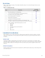
Page 27: ... following for each input Aspect ratio Brightness Contrast Color temperature and white balance Color level Tint Input position 41 Installation Considerations Proper installation of your display will ensure a satisfying viewing experience Whether a display is installed temporarily or permanently the following should be taken into account to ensure the best performance of the display Ambient Light I...

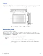
Page 28: ...ide to wall mount the display ensure that the wall mount bracket is installed according to the instructions included with it The wall must be capable of supporting a redundant weight factor three 3 times the weight of the display or be reinforced We recommend that this be done by a custom installation specialist NOTE To safely mount the display on a wall Use only the approved wall mount kit design...

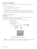
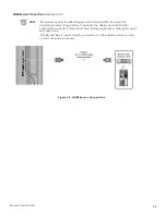
Page 29: ...re provided in the packaging box Ensure that the cables are securely connected Tighten the thumbscrews on connectors that have them Connecting a Control System or PC RS 232 Connection Use a straight through RS 232 cable with a 9 pin male connector to connect a PC or control automation system if present to the RS 232 port on the display see Figure 3 2 For more information about using this connectio...

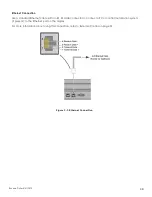
Page 30: ...ndard Ethernet cable with an RJ 45 male connector to connect a PC or control automation system if present to the Ethernet port on the display For more information about using this connection refer to External Control on page 53 Figure 3 3 Ethernet Connection ...

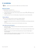
Page 31: ... 31 Connecting Source Componentstothe Display Connect your video sources to the display as shown and described in the sections that follow DisplayPort Source Connection See Figure 3 4 Figure 3 4 DisplayPort Source Connection ...

Page 32: ... DDC standard This standard provides Plug and Play capability the display and a VESA DDC compatible computer communicate their setting requirements allowing for quick and easy setup For Plug and Play to work correctly you must turn on the display before you turn on the connected computer Figure 3 5 HDMI Source Connections ...

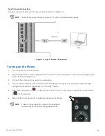
Page 33: ...C receptacle on the side of the display AC 100V 240V See Figure 2 2 3 Connect the other end to your AC power source 4 Turn on the main power switch at the side of the display see Figure 2 1 The power indicator lights orange to indicate that the display is in standby mode 5 Press the power button on the remote control to turn on the display or press the power button on the keypad 6 After a brief wa...

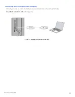
Page 34: ...C or the provided USB cable for DispalyPort and HDMI source connections Make sure connect the cable to the display by following the corresponding indicating dots on I O ports See Figure 3 7 The video output from the computer is connected to a video input on the display See Figure 3 4 Figure 3 5 or Figure 3 6 The display is turned on Using the Remote Control push the source button and select the so...

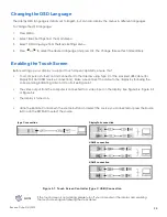
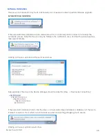
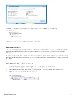
Page 35: ...s Note that the icon may be hidden in the notification area and that the procedure may take several minutes Clicking on the pop up ballon at this point would show Fully expanded the view in the Device Manager should look like this View Devices by connection If the automatic installation fails to find the driver or if automatic driver installation is disabled or if there is no Internet connection t...

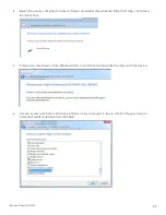
Page 36: ...ch device connected to the computer the driver can be installed manually The driver provided with this upgrade package was downloaded from http catalog update microsoft com requires Internet Explorer and is called Microsoft Other hardware WinUsb Device version 1 1 0 0 from 2012 08 30 Manual Driver Installation Device Connected 1 Extract the firmware upgrade zip file right click Extract all to the ...

Page 37: ...ed folder from step 1 and follow the instructions 5 If step 4 was unsuccessful then Windows failed to automatically associate the driver with the device 6 Choose Let me pick from a list if device drivers on my computer in step 4 scroll all the way down to Universal Serial Bus devices and click Next ...

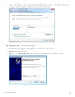
Page 38: ...w the steps under Manual Driver Installation Device Not Connected first Manual Driver Installation Device Not Connected 1 Extract the firmware upgrade zip file right click Extract all to the Desktop 2 Navigate to the support folder 3 Right click on the install_driver bat file and select Run as administrator and follow the instructions ...

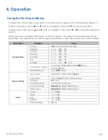
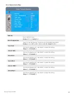
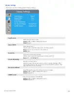
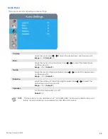
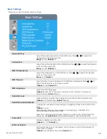
Page 39: ...l characteristics some menu options may not be available Main Menu SubMenu Value Image Settings Scheme User Vivid Cinema Game Sport Brightness 0 1 2 50 100 Contrast 0 1 2 50 100 Sharpness 0 1 2 50 100 Saturation 0 1 2 50 100 Hue 0 1 2 50 100 Backlight 0 1 2 50 80 100 Color Temp Gamma Color Temp 5000K 6500K 7500K 9300K User Gamma 2 2 off HDMI RGB Range Auto 0 255 16 235 Display Settings Input Sourc...

Page 40: ... Input Mapping Auto USB Touch 1 USB Touch 2 USB Touch 3 Game Mode On Off USB Settings On Off Touch USB HID USB Audio USB External USB LAN USB Network Configuration Telemetry Interval 1 60 seconds 5 Firmware Update USB Yes No IoT Firmware Update Yes No Restore Factory Default Yes No Information Source Shows the Name of Input Source Resolution Shows the Current Resolution Temperature Show the Temper...

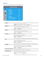
Page 41: ...or to select the desired level and then press OK Range 0 100 Default 50 Note This function is not available when displaying PC or graphics sources Hue Increase or decrease the green hue Press or to select the desired level and then press OK Range 0 100 Default 50 Note This function is not available when displaying PC or graphics sources Backlight Increase or decrease the intensity of the LCD backl...

Page 42: ...t this setting Range 0 100 Default 50 Green Gain Set Color Temperature to User Mode to adjust this setting Range 0 100 Default 50 Blue Gain Set Color Temperature to User Mode to adjust this setting Range 0 100 Default 50 Red Offset Set Color Temperature to User Mode to adjust this setting Range 0 100 Default 50 Green Offset Set Color Temperature to User Mode to adjust this setting Range 0 100 Defa...

Page 43: ...the overscan of the image Press or to select the desired level and then press OK Range 0 10 Default 0 Source Renaming Rename the input source Press OK to select the input source you want to rename Using or to change the character and or to move forward back a position Then press OK button to save the name No Source Default Select the Input Source when all input source is no signal Options HDMI 2 H...

Page 44: ...t the desired level and then press OK Range 0 100 Default 70 Bass Adjust the sound in low tones bass Press or to select the desired level and then press OK Range 10 10 Default 0 Treble Adjust the sound in high tones treble Press or to select the desired level and then press OK Range 10 10 Default 0 Balance Adjust the balance of the left and right speakers Press or to select the desired level and t...

Page 45: ...s OSD Language Select the OSD language Options English French Spanish German Dutch Swedish Portuguese Danish Italian Default English Splash Screen Select whether a splash screen appears when the monitor is powered up Options Off Default User Default Default Splash Screen Download Change the user splash screen image by plugging a thumb drive into Service port Options Yes No Note The file name must ...

Page 46: ...a of the DisplayPort HDMI 2 3 Type C inputs Options 1080p 4K2K 30 4K2K 60 Default 4K2K 60 Note Use the 1080p setting for the broadest support of lower resolution sources Use 4K2K setting to support high resolution sources such as 3840x2160 Touch Input Mapping Select one of the touch connections or choose auto detection Options Auto USB Touch 1 USB Touch 2 USB Touch 3 Default Auto Game Mode Select ...

Page 47: ...ll settings to their default value Options No Yes Note To reset network connection to default must go to Network Configuration Load Default and select Yes to restore Wake Up from Sleep By default the display will enter power saving Sleep Mode if no signal is received for 5 minutes Normally the Type C RS 232 DisplayPort and HDMI inputs are inactive in Sleep Mode to save power To change the behavior...

Page 48: ...P or the static IP address of the display s Ethernet port Default 0 0 0 0 Netmask Set the subnet mask address Default 0 0 0 0 Gateway Set the Gateway mask address Default 0 0 0 0 DNS Set the DNS mask address Default 0 0 0 0 Save Settings Save the network settings and apply to device Refresh Refresh dynamic IP information Load Default Load default communication settings Options No Yes MAC Address D...

Page 49: ...t Source Resolution Show the Current Resolution Temperature Display room temperature data both in C and F Ambient Light Display room brightness data in lux Presence Display proximity status Detected Yes undetected No IoT Status Display IoT connection status Status connecting connected Model Name AVW 6555 Firmware Version Show the Firmware Version of the Monitor Serial Number Show the Serial Number...

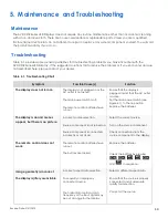
Page 50: ... main power switch is off The remote control batteries have run out Ensure that the display is plugged in and that the AC outlet is active Set the main power switch see Figure 2 1 to the on position Replace the batteries The display is on and menus appear but there is no picture Incorrect source selection Source component is not turned on Source component is connected incorrectly or not at all Sel...

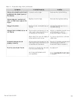
Page 51: ...ution and frequency of the video card in the computer are not compatible with the display HDMI cable from source to display is either defective or too long Select a compatible resolution and vertical frequency refer to Supported Timings on page 61 Try a known good and or shorter HDMI cable Computer images do not display correctly The resolution and frequency of the video card in the computer are n...

Page 52: ...re fault please contact the support line below You will require your unit serial number The operator will attempt to diagnose any fault and will take action as appropriate Warranty Support UK EMEA Tel 44 0 1276 804 654 service avocor co uk US ROW Tel 858 268 7999 service avocor com ...

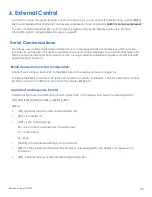
Page 53: ...erminal emulation program such as Windows HyperTerminal or Tera Term RS232 Connection and Port Configuration Connect your control system or PC to the RS232 input of the display as shown in Figure 3 2 Configure the RS232 controller or PC serial port as follows no parity 8 data bits 1 stop bit and no flow control Set the baud rate to 115200 to match that of the display RS232 port Command and Respons...

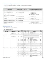
Page 54: ... 01 00 47 56 45 S 0 S 5 08 S 0 S 5 the firmware version in ASCII Serial Command List Table 6 2 lists all supported commands Table 6 2 Serial Commands Main Item Control Item Type CMD HEX Value HEX Reply HEX Content CMD ASCII Power Control and Input Source Power Control W R 50 4F 57 Note 0 0 Off soft power POW 1 1 On soft power Input Source W R 4D 49 4E 9 9 HDMI 2 MIN 0A 0A HDMI 3 0D 0D DisplayPort1...

Page 55: ... Other Control Scaling W R 41 53 50 0 0 Main Window Aspect Ratio Native PointToPoint ASP 1 1 Full Screen 16 9 2 2 Pillarbox 4 3 3 3 Letterbox 4 4 Auto W R 5A 4F 4D 00 0A 00 0A Adjust overscan ratio ZOM Other Control W 52 43 55 0 0 MENU Key RCU 1 1 INFO Key 2 2 UP Key 3 3 DOWN Key 4 4 LEFT Key 5 5 RIGHT Key 6 6 OK Key 7 7 EXIT Key 0A 0A HDMI2 Key 0B 0B HDMI3 Key 17 17 SCALING Key 18 18 FREEZE Key 1...

Page 56: ...0 10 TRE W R 42 41 4C 00 14 00 14 Bass 10 10 BAL W R 49 4E 53 0 0 Internal Speaker Off INS 1 1 Internal Speaker On W R 4D 55 54 0 0 Mute Off MUT 1 1 Mute On Scheme selection W R 53 43 4D 0 0 User SCM 1 1 Sport 2 2 Game 3 3 Cinema 4 4 Vivid Other Control EcoMode WakeUpFromSleep W R 57 46 53 0 0 No WFS 1 1 Yes 2 2 Never Sleep RTC W R 52 54 59 00 63 00 63 Set Real time Year RTY W R 52 54 4D 01 0C 01 ...

Page 57: ... 46 4D 00 3B 00 3B Tuesday Off Minute EFM W R 44 4E 48 00 17 00 17 Wednesday On Hour DNH W R 44 4E 4D 00 3B 00 3B Wednesday On Minute DNM W R 44 46 48 00 17 00 17 Wednesday Off Hour DFH W R 44 46 4D 00 3B 00 3B Wednesday Off Minute DFM W R 55 4E 48 00 17 00 17 Thursday On Hour UNH W R 55 4E 4D 00 3B 00 3B Thursday On Minute UNM W R 55 46 48 00 17 00 17 Thursday Off Hour UFH W R 55 46 4D 00 3B 00 3...

Page 58: ...Full Range 2 2 Limited Range Touch Control W R 54 4F 43 0 0 Auto TOC 2 2 USB Touch 1 3 3 USB Touch 2 4 4 USB Touch 3 OSD Control Transparency W R 4F 53 54 00 04 00 04 OSD Transparency OST H Position W R 4F 53 48 00 64 00 64 OSD H Position OSH V Position W R 4F 53 56 00 64 00 64 OSD V Position OSV OSD Language W R 4F 53 4C 0 0 English OSL 1 1 French 2 2 German 3 3 Dutch 08 08 Danish 0D 0D Italian 0...

Page 59: ...e for the display is 16559 decimal 0x40AF binary 01000000 10101111 16 data bits eight 8 bits for the command followed by the logical inverse of the command An end pulse a modulated pulse of 0 56 ms similar to the modulated pulse in the 0 and 1 bits The end of the modulated pulse constitutes the end of the data transmission The carrier frequency is 38 kHz with the modulated pulses having a 33 duty ...

Page 60: ...NS DRC EQ Camera Resolution 6 element aspherical glass lens HD 1080P 30fps CMOS AE AWB AF AGC WDR super wide 120 FoV AZURE SMART SPACES DATA Sensors Temperature 5 45 C 3 C Brightness 0 3000 lux Presence 3 5 0 5M CONNECTIVITY Connections 2 x HDMI 2 0 1 x DisplayPort 1 2 1 x Type C Audio Audio In Audio Out SPDIF Out Control 1 x USB 3 0 HUB 3 x Touch USB 3 0 RS232 Ethernet IR PHYSICAL SPECIFICATIONS ...

Page 61: ...59 995 68 25 O 1280 x 800 49 306 59 91 71 O O O 49 702 59 81 83 O O O SXGA 1152x864 67 5 75 108 O O O 1280x1024 63 981 60 02 108 O O O 79 976 75 025 135 O O O 1440 x 900 55 469 59 901 88 75 O 55 935 59 88 106 5 O O O WSXGA 1680 x1050 64 674 59 883 119 O O O 65 29 59 954 146 25 O O O UXGA 1600 x 1200 75 60 162 O O O 1920 x 1080 66 587 59 93 138 5 O WUXA 1920 x 1200 74 038 59 95 154 O QHD 2560x1440 ...

Page 62: ...n Date 5 31 2019 62 Timing fH kHz fV Hz Dot clock MHz HDMI Type C DisplayPort 4K2K 3840x2160 54 24 297 O O O 56 25 25 297 O O O 67 5 30 297 O O O 112 5 50 594 O O O 133 313 59 997 533 25 O O O 135 60 594 O O O ...

Page 63: ...Revision Date 5 31 2019 63 Overall Dimensions Figure 7 1 shows the display dimensions of AVW 6555 all dimensions are in inches Figure 7 1 AVW 6555 Display Dimensions inch ...

Page 64: ...Revision Date 5 31 2019 64 Figure 7 2 shows the display dimensions of AVW 6555 all dimensions are in millimeters Figure 7 2 AVW 6555 Display Dimensions mm ...

Page 65: ...Revision Date 5 31 2019 65 Notes ...

Page 66: ... Attempting to move the display with one person may result in dropping the display and or serious injury When moving a display in its shipping carton lift the carton using the white handles Carrying the Display This display is heavy please follow proper lifting technique as pictured below Failure to do so may cause injury OK AVOID ...

Page 67: ... is strong enough to hold the necessary weight of the display and the mount Step1 Keep the display facing the ground and place it on a flat object Step2 Remove the screws M8 15 from the back of the display Step3 Align the wall brackets with the mounting holes and attach the brackets to the display using the screws removed in Step 2 Caution Longer screws will damage the display NOTE To safely mount...

Page 68: ...VESA Adapter Attach the supplied VESA adapter plate to the back of the display making sure the plate and the mounting holes align Step 2 Secure the plate in position with the four provided screws size M4 6 NOTE The VESA adapter plate is compatible for NUC s or Backpacks that have VESA mounting patterns of 75 x 75 and 100 x 100 Use maximum 6mm 0 24 long screws 4mm 0 16 Metric ...

Page 69: ...Revision Date 5 31 2019 69 Appendix IV Wall Mount Safety Notes ...

Page 70: ...Revision Date 5 31 2019 70 ...

Page 71: ...device 1 Enter OSD menu then go to Adv Settings and select Network Configuration 2 Configure network settings you can select Dynamic IP to Disable or Enable the default setting is Enable 3 Once the network setup is done the IP and MAC address will be shown on Network Configuration menu ...

Page 72: ...t the IP address and press Enter the Login window will pop up 2 Enter the username and password then click the LOGIN button Default Username admin Default Password system Configure Network Settings When Enable DHCP is On all the columns of Nerwork Setup are unable to edit ...

Page 73: ...ange the IP Address Subnet Mask Default Gateway and Primary DNS in Network Setup Any changes that you make are automatically synchronized to OSD Network Configurations Modify Admin Setup To change the default username and password and click Apply Changes to save ...

Page 74: ...Revision Date 5 31 2019 74 Update IoT Module Firmware You can update the IoT Module Firmware by inserting the firmware file URL here ...

Page 75: ...gister a new device identity in the IoT hub Copy the device s Connection string primary key to use it on IoT Module later For more information see Microsoft Azure IoT Hub Setup and Device Registration 3 Go back to IoT Module then paste the Device Connection String and click Apply Changes to enable secure access to the IoT hub 4 After completing all the above setups you can check the sensor data in...

Page 76: ...and the general information of the display Configures Sensor Timer Setup To change Sensor Telemetry Interval range from 1 60 seconds Any changes that you save are automatically synchronized to OSD Adv Settings Note Presence Detection Timer is for display only you can edit on OSD menu Adv Settings ...

Reviews: