www.avonic.eu
6
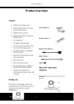
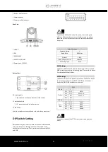
2 Remote Control Sensor
3 Power Indicator
4 Communication Indicator
Rear Part
5 USB3.0
6 DVI
7 RS-232IN/IR
8 RS-232OUT/RS-485
9 Power Input
(
DC12V
)
Bottom Part
10 Locating Hole
Used to define installation direction of the camera.
11 Installation Hole
1/4” inch screw, used to fix the camera.
12 DIP Switch
Used to set address, protocol, baud rate and other parameters.
DIP Switch Setting
Before operating the camera, please set camera’s address, baud
rate protocol and etc. through its DIP switch located at the
bottom part of the camera. There are two switches named SW1
and SW2.
Note
The SW1 and SW2 switches look the same, their settings are
different. SW1 is used to set camera’s address and mounting
types, while SW2 is used to set camera’s control protocol and
baud rate
Default Settings
Camera Address
1
Baud Rate
9600bps
Protocol
VISCA
Video Output Format
1080P25
Mounting Type
Stand
SW1 Settings
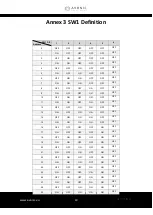
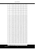
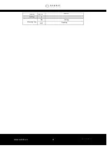
Use DIP1 to DIP6 to set 64 address accordingly. DIP7 is reserved.
DIP8 is used to set camera’s mounting type. Please refer to Annex
3 for detailed SW1 definitions.
SW2 Settings
Use SW2 to set
camera’s protocol, baud rate. Use DIP1 and DIP2
to set camera’s protocol, use DIP 3 and DIP4 to set camera’s
baud rate. DIP5~DIP8 switches are reserved.
Note
It requires a reboot of the PTZ for the switch setting to take
effect
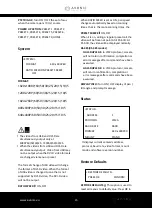
SW2
DIP No.
1
2
Protocol
OFF
OFF
VISCA
ON
OFF
PELCO- D
OFF
ON
PELCO- P
ON
ON
-
DIP No.
3
4
Baud
Rate
OFF
OFF
2400
ON
OFF
4800
OFF
ON
9600
ON
ON
38400
Summary of Contents for CM55-VCU
Page 4: ...www avonic eu 4 Troubleshooting 22...
Page 11: ...www avonic eu 11...
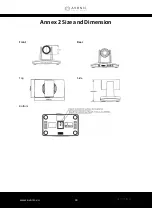
Page 18: ...www avonic eu 18 Annex 2 Size and Dimension Front Rear Top Side Bottom...
Page 21: ...www avonic eu 21 reserve reserve reserve DIP No 8 Mounting Type ON Ceiling OFF Desktop...
Page 23: ...www avonic eu 23...
Page 24: ...www avonic eu 24 CM55 VCUSB3 0 MAN2 2 Avonic 2017...


