

- 11 -
Code (Rolling Code)
The Transmitter microprocessor generates a code that is transmitted through the LEDs to the
Receiver, that elaborates the code, sending again to the TX via the Synchronisation wire. Once
arrived to the TX microprocessor the code is compared with the original one.
The interruption or the manipulation of this flow generates an alarm situation.
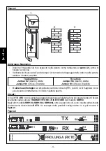
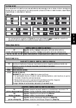
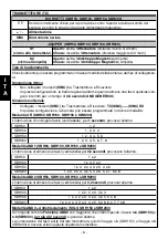
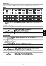
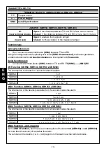
Function with serial synchronism
Using the configuration with serial synchronism
(SINC connected)
, the barrier
functions: OR, AND1, AND2, and, for SBH 150 - 200, AND2 + anti-creeping.
Function with optical synchronism
Using the configuration with optical synchronism
(SINC disconnected),
the barrier generates an
alarm situation when
at least two beams
are interrupted for
0,5 seconds
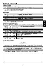
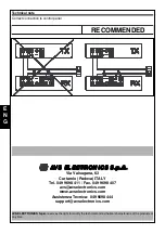
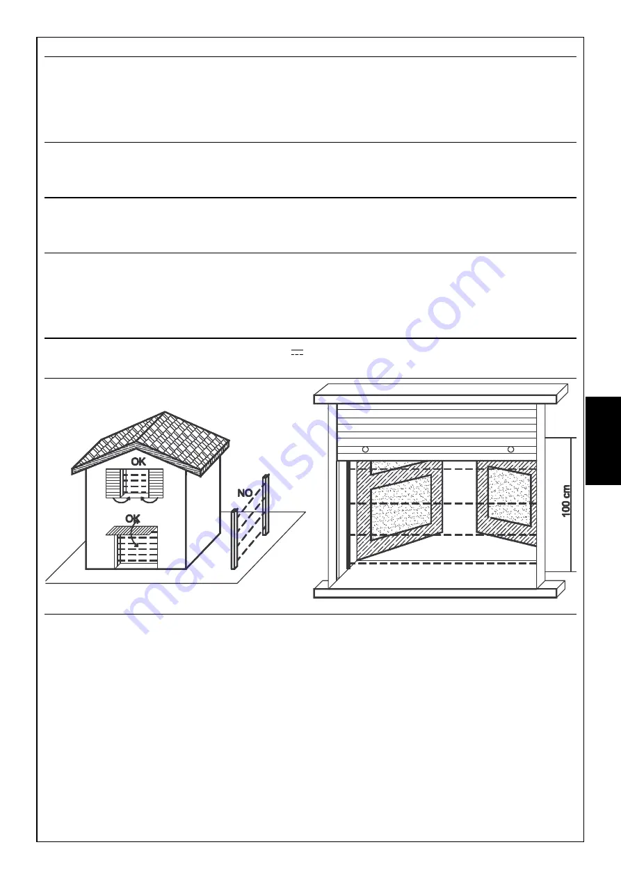
Avoid
•
to paint frontally the Silver
•
to put Silver directly in front of the sun
•
to remove the protection of optical groups inside the barriers
•
the direct contact with rain.
Use
•
Use stabilized power supply units 13,8V , not switching.
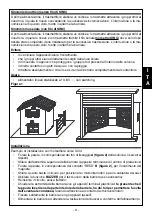
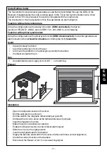
Picture1
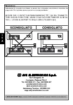
Installation
•
Open the tail plastic covers of the silver
•
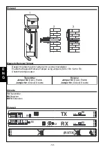
Drill the wall (point A, picture 2)
•
Drill the wall for the magnetic removal tamper (point B)
•
Unthread the circuit to arrive at the terminal blocks and jumpers
•
Insert the magnet in the hole
•
Make the wire connections as needed
•
Enable the Buzzer function to check Silver alarm signal
•
Slide the circuit on the right position
•
Insert the tail plastic and fix the barrier
•
Supply the barriers and wait for the buzzer off (this confirms a correct alignment)
•
Check the correct function of the barriers
•
Disconnect the Buzzer or turn it on as a warning signal
E
N
G


