background image

6

BACK

SET UP-ASSEMBLY 

MECHANICAL HAZARDS

Projection surface damage in case of faulty assembly or set up.

Make sure all frame parts assembled correctly and all hinges and joints are locked before one unfold and 

attach the projection surface.

FRAME AND LEG COMPONENTS

Please be careful 

not to pinch 

your fingers!

FALLING OVER

WARNING

Falling over of a projection screen can cause severe injury or death! 

To avoid falling over:

•  Make sure that the projection screen is in level.

•  Mind the maximum set-up height of the legs - Please follow the instructions in chapter LEG HEIGHTS (site 10)

•  Prevent air draft 

• 

Use additional weights on the base profile of the leg to gain higher stability.

•  Use suspension points (e.g.: EasyFly) according to the overall system weight for additional safeguarding.

• 

Do not put additional load on the screen frame!

• 

Do not use outdoors!

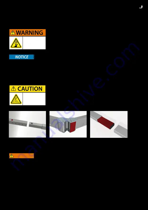
Foldable snap joints, corner hinges and plug-in connections can 

lead to injury to the hands (body parts). Please be careful not to 

pinch your fingers!

Danger of injury due to improper assembly. 

Make sure all frame parts assembled correctly and all hinges 

and joints are locked before raising screen to standing 

position. Falling parts can cause severe injury or death!

Summary of Contents for T32-SHIFT

Page 1: ...03BV T32 SHIFT INSTRUCTION FOR MOBILE PROJECTION SCREENS ...

Page 2: ...gy Special extruded and hardened aluminum alloy allows maximum stability at minimum weight FRAME ADAPTER Frame adapter und transport lock in yellow bag PROJECTION SCREEN BAG Lined storage bag for projection screen T32 SHIFT EXTENSION T32 SHIFT EXTENSION 110 cm 55 cm T32 SHIFT ENDMODULE ...

Page 3: ...AG WITH WHEELS padded tearproof nylonbag with wheels and carrying straps small 128x25x30 cm big 133x31x35 cm T32 SHIFT BASIC MODULE 116 cm on transport profile ASSEMBLY INSTRUCTION LOCKING AND SLIDING MODULE ...

Page 4: ...TION 5 SAFETY 5 OPERATION MAINTENANCE AND SERVICE 8 WARRANTY 9 LEG VARIANTS 10 ADAPTION AND ASSEMBLY 11 ADAPTERS 12 ATTACHING THE T32 SHIFT LEGS 13 EXTENSION PARTS 15 HEIGHT ADJUSTMENT 16 DISASSAMBLY 17 TRANSPORT LOCK BOLTS 17 SUBSEQUENT VARIO FRAME MODIFICATION 18 ...

Page 5: ...abels on each component and on the labeled soft bags roller bags or flight cases SAFETY GENERAL INFORMATION FOR THE MANUAL AND SAFETY This operating manual forms part of the projection screen system and enables a safe and efficient operation The safety section provides information about important safety aspects for the protection of persons frame and projection materials Task related warnings note...

Page 6: ...t of the legs Please follow the instructions in chapter LEG HEIGHTS site 10 Prevent air draft Use additional weights on the base profile of the leg to gain higher stability Use suspension points e g EasyFly according to the overall system weight for additional safeguarding Do not put additional load on the screen frame Do not use outdoors Foldable snap joints corner hinges and plug in connections ...

Page 7: ...screen then all plug in and clamp connections must be secured against becoming loose and falling It is not allowed to use the projection surface holding the frame parts in position Falling parts can cause severe injury or death Please make sure that all components are secured safely before raising screen to standing position and lifting Use the necessary number of suspension points e g EasyFly acc...

Page 8: ...nap buttons and surface to avoid permanent marks Additionally following instructions have to be adhered to Do not allow the projection surface to get in contact with sharp objects Do not bring printed and coloring objects instructions magazines etc in contact with the surface Do not write on the projection surface Colors penetrate the projection surface and cannot be cleaned anymore COLD BREAK A p...

Page 9: ...mply with the local safety regulations Inappropriate use misuse Use of unauthorized and non trained staff Unauthorized equipment conversions and technical modifications by the operator himself Use of spare parts not approved by the manufacturer Typesetting and print errors Failure to observe the above points will invalidate the warranty claims Technical specifications are subject to change without...

Page 10: ...of the bottom edge of the frame without additional safeguarding Set up heights are points of reference and have to be adapted in accordance with the screen size and ambient conditions Set up heights are based on absolute vertical alignment at indoors without additional force effects e g wind air condition draught 46 118cm min 2 5cm max 28 70cm 68 173cm min 2 5cm max 49 125 cm 90 228cm min 2 5cm ma...

Page 11: ...e with the T32 SHIFT legs you have to attach adapters to the backside of the frame once only 1 7 Unfold the screen frame with the backside facing upwards Open the folded frame horizontally 1 3 and then vertically 4 5 The locking hinges engage and lock automatically 6 7 Beware of pinch points ...

Page 12: ...PTERS 1 4 Attach the frame adapters to the round spacers on the backside of the screen with the enclosed countersunk screws using the hexagonal spanner 5 7 Flip the frame and attach the projection surface Beware of pinch points ...

Page 13: ...t the leg components next to each bottom corner of the frame Each component is labeled either with a red or green square which indicates the corresponding side of the frame 3 Start with the base module Open and secure the base bars Beware of pinch points ...

Page 14: ...t slide the locking module onto the lowest point of the base module Make sure that the colored squares match 8 9 Lift the base module and place the locking module onto the frame adapter in a horizontal position 10 Secure the bayonet coupling by turning the base module in a vertical position Beware of pinch points ...

Page 15: ...mponents so that the colored labels are on the same side The snap lock will engage automatically 3 6 Attach the sliding module in a slightly off axis angle Check that the colored labels are matching and slide in the extension parts 7 Turn the extension parts vertically and connect them with the base module Beware of pinch points ...

Page 16: ... can start at the bottom of the scale and simply move the screen up to the preferred position The T32 SHIFT will lock automatically The height can be adjusted in one inch steps 2 54cm No extra measuring is needed to ensure the frame is level due to clearly marked height scales ...

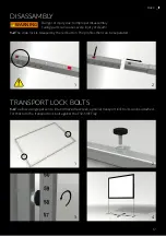
Page 17: ...tional transport lock bolts can be attached For that turn the transport lock bolt against the T32 SHIFT leg DISASSAMBLY WARNING 1 2 The snap lock is released by the red button The profiles then can be separated Danger of injury due to improper disassembly Falling parts can cause severe injury or death ...

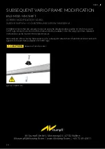
Page 18: ...CREW M6X30MM All VARIO screens that are already in use can easily be adapted subsequently on site for use with SHIFT legs All one must do is to drill a hole and bolt an adapter onto the plug in profiles Detailed instructions can be found in the related manual Optionally we offer a factory based service of a subsequent attachment of additional insert nuts with spacers to mount frame adapters for SH...

Reviews: