Ý
ØßÐÌÛÎ
ï
| Introduction
RG300 Hardware Description
18
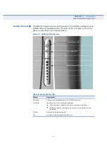
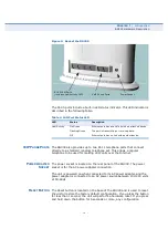
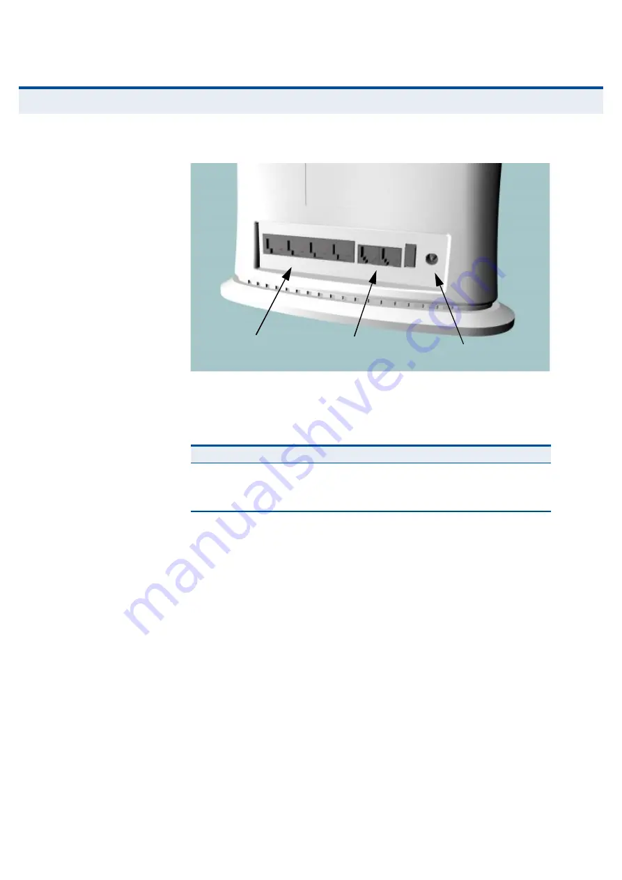
Figure 3: Back of the RG300
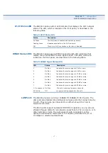
The RJ-45 ports include a built-in LED status indicator. This LED indicator is
described in the following table.
Ê
Ñ
×Ð Ð
ØÑÒÛ
Ð
ÑÎÌÍ
The RG300 also provides up to two RJ-11 telephone ports that connect
directly to a standard (analog) telephone set. This allows a regular
telephone to be used for making VoIP calls over the Internet.
Ð
ÑÉÛÎ
ß
ÜßÐÌÛÎ
Í
ÑÝÕÛÌ
The power socket is located on the rear panel of the RG300. The power
socket is for the AC power adapter connection.
The unit is powered on when connected to its AC power adapter, and the
power adapter is connected to an AC power source between 100-240 volts
at 50-60Hz.
Î
ÛÍÛÌ
Þ
ËÌÌÑÒ
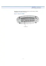
The Reset button is located on the base of the RG300 and is used to reset
the unit or restore the factory default configuration. If you press the button
for less than 1 second, the unit will perform a hardware reset. If you press
and hold down the button for 5 seconds or more, any configuration
Table 4: LAN Port Status LED
LED
Status
Description
Link/Activity
On Green
Ethernet port has a valid link with an attached device.
Flashing Green
The port is transmitting or receiving data.
Off
Ethernet port has no link with another device.
RJ-45 LAN Ports
(includes Link/Activity LED)
VoIP Phone Ports
Power Socket

