18
S
U
S
P
E
N
S
I
O
N
S
E
T
T
I
N
G
T
E
C
H
N
I
Q
U
E
C
a
mb
er
a
d
j
u
s
t
m
e
n
t
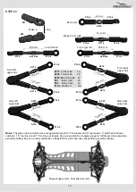
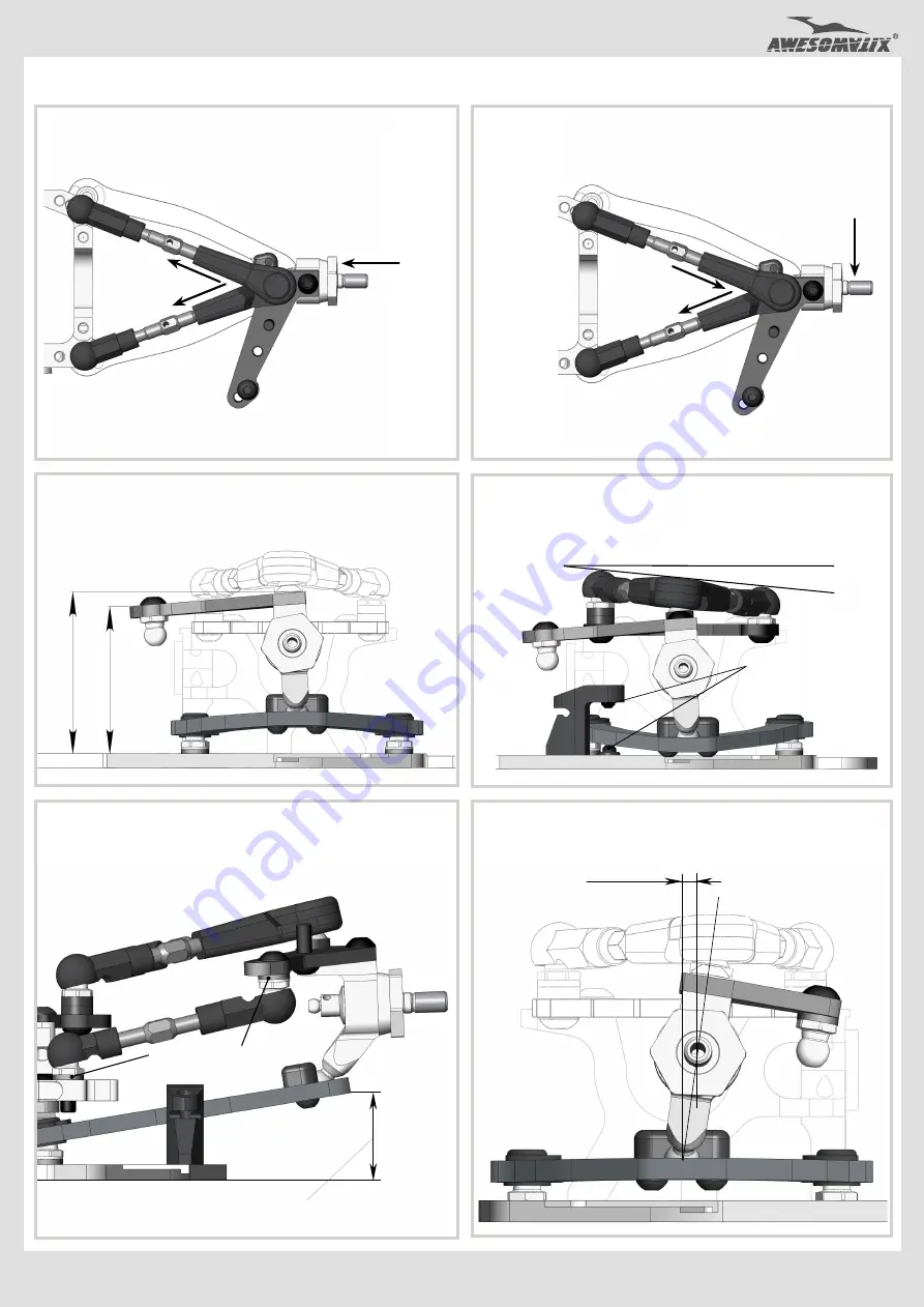
rule
:
S
imultaneous
both
upper rods
0.5mm
shorten
i
ng
(1/2 turn of both turnbuckles)
a
dds
1.0
°
o
f
c
am
b
er
angle
at
c
onstant
c
aster
.
C
a
s
t
er
a
d
j
u
s
t
ment
rule
:
Simultaneous
f
r
ont
upper rod
0.5mm
elongation
an
d
rear u
pp
er ro
d
0
.
5
mm
shorten
i
ng
a
dds
2.5
° of
c
a
s
t
e
r
at constant camber
.
W
h
ee
l
b
a
s
e
a
d
j
u
s
t
ment
:
U
s
e rear sus
p
ens
i
on
c
ast
e
r
ch
an
g
e
for
this adjustment
.
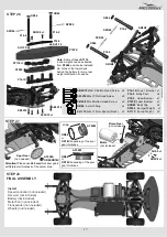
Adding 4°caster shortens wheelbase by 1mm.
U
se
R
id
e
H
eight Gauge for
U
pstop
&
Downstop
measuring.
R
e
a
c
t
i
ve
C
a
s
t
er
sett
i
n
g
i
s
p
oss
i
b
le
.
U
s
e
SS
3X
4
screws
for Upstop
and
Downstop s
ett
i
n
g
.
R
oll Center adjustment
:
U
s
e
combinations of
S
H
0
.
5
,
S
H
1
.
0
a
n
d
S
H
1
.
75
Sp
acer
s
u
n
der
a
p
p
ro
p
r
i
a
t
e
Pivot Balls and Ball Studs
f
o
r
this adjustment
.
Adjust these spacers
for
Bump Steer control.
C
a
s
t
er
m
e
a
s
u
r
in
g
:
C
aster
angle
°
=
(H1
-
H2)*1.
5
for front
(H1-H2)*2.
2
for rear
H
1
H
2
A
t
t
e
n
t
ion
!
I
nstall
SH12
X
1.5 Spacers on the rear
AT13FX Wheel Hexes at using of the set-up stations.


