background image

MPR-3014WF-xM

- 9 -

  Doc# 041314

AWID PROPRIETARY

Verify that all items listed below are present before starting the installation.

a. 

Sentinel-Sense 

MPR-3014WF-xM     

Qty=1

b. 

ANT-915-CPS-A       

Qty=1~4 

or 

8

c. 

RTC08/16/24        

Qty=1~4 

or 

8

d. 

Documentation 

Demo 

Program 

CD    

Qty=1

e. 827-06W   Reader mounting bracket (Optional)
f. 12 VDC wall plug power supply unit (AWID P/N PS12-3.3AR)  Qty=1

3.2. PREPARATION FOR INSTALLATION

3.2.1.  Bench Top Verification

It is always a good idea to verify system operation before committing to a full-scale
installation. The following are the necessary steps to test reader s operation in a static
environment.

·

  Connect reader to Network with a network cable at the TCP/IP port

·

  Connect the power jack from the wall plug power supply to reader

·

  Load the demo program CD onto (installation) PC and launch the demo program.

Try Connect after filling in the IP address of reader and then some commands.

3.2.2.  Aiming of Antenna

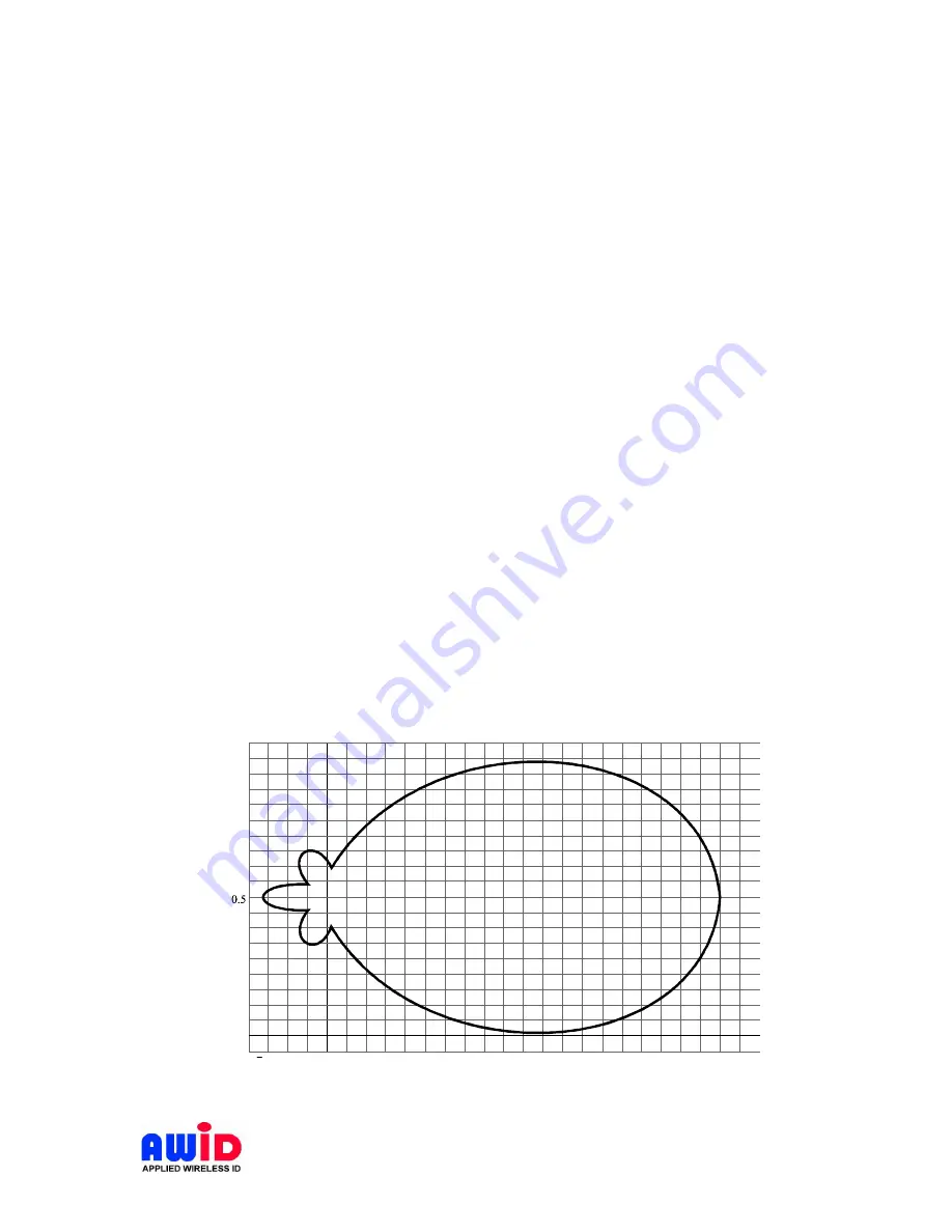
Antenna Pattern for MPR-3014WF-xM

MPR-3014WF-xM comes with a set of (up to 4 or 8) antennas each circular polarized to
ensure reading tag with random orientation. Most circular polarized antenna has a
horizontal to vertical differential of up to 3 dB, this will cause the antenna pattern to
deviate from a true circle. AWID s antenna has a horizontal to vertical differential of
typically less than 0.5 dB, making the antenna pattern as near to a circle as possible.

0.15

0

0.25

0.5

0.75

R

0

Distance (R)

W

id

th

(

W

)

W (0.72R)

Figure 1 MPR-3014WF Antenna Pattern

Summary of Contents for SENTINEL-SENSE MPR-3014

Page 1: ...MPR 3014WF xM 1 Doc 041314 AWID PROPRIETARY SENTINEL SENSE MPR 3014 MPR 3014WF xM Installation Operation Manual...

Page 2: ...erference when the equipment is operated in a commercial environment This equipment generates uses and can radiate radio frequency energy and if not installed and used in accordance with instruction m...

Page 3: ...Patch To reduce potential radio interference to other users the antenna type and its gain should be so chosen that the equivalent isotropically radiated power EIRP is not more than that required for s...

Page 4: ...2 2 Aiming of Antenna 9 3 3 INSTALLATION STEPS 10 4 NOTES ON SOFTWARE PROGRAMMING AND SYSTEM OPERATION 11 4 1 SET UP AND SYSTEM OPERATION 11 4 1 1 Setting Up MPR 3014WF xM 11 4 1 2 Running a Custom So...

Page 5: ...our 4 inputs four 4 outputs that work with all leading passive UHF passive tags Each of these readers comes with a unique combination of long read range small size and low power consumption Its primar...

Page 6: ...h optically isolated GP I O Splash proof design for indoor or outdoor applications 1 2 MODEL NUMBER ASSIGNMENT Multi Antenna Readers MPR 3014WF xM YZ MPR Multiple protocol RFID WF WinCE Fixed location...

Page 7: ...12 VDC Input current 12VDC 3 3 amp 2 1 CHANNEL FREQUENCY TABLE Frequency range 902 928 MHz Minimum number of frequency channels 50 CH 902 928 MHz CH 902 928 MHz CH 902 928 MHz CH 902 928 MHz CH 902 9...

Page 8: ...d loop considerations 2 2 2 RS 232 Pin Function description Pin Function description 1 DCD 5 GND 2 RXD 6 DSR 3 TXD 7 RTS 4 DTR 8 CTS 2 3 MEASURING READ DISTANCE Make sure you know the tag types For in...

Page 9: ...work with a network cable at the TCP IP port Connect the power jack from the wall plug power supply to reader Load the demo program CD onto installation PC and launch the demo program Try Connect afte...

Page 10: ...INSTALLATION STEPS Check to ensure that all connections are secure Make sure all wires through the cable clamps are anchored properly avoid dangling wires that may become safety hazard Mount the Read...

Page 11: ...der response will become sluggish Mixed Mode This mode assumes the user is aware of the types of protocol in use and furthermore the user made a determined effort to operate the reader in a mixed prot...

Page 12: ...application which is NET based with easy to follow GUI operations simply fill in the IP address of MPR 3014WF xM installed then click Connect should get you started 5 Appendix 5 1 SAMPLE GPIO APPLICAT...

Reviews: