background image


Page |  15


Step 10: Attaching the (m) Projection Arms to the Surface


10a) 

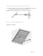
Once the (m) projection arms are attached, plate of the (n) Wall Bracket against your surface and 
mount it with the specified hardware for your surface. Refer to Figure A10


Figure A10.1:

 Install the (n)

 Wall Bracket to the (m) Projection Arms and to the Wall


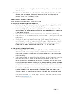
Step 11: Your Finished Bahama Awning!


Figure A11.1:

 Final Installation


Summary of Contents for BAHAMA

Page 1: ...of the Bahama Frame 6 Step 3 Installing the e e2 Middle Support s to the b3 Full Top Bar 7 Step 4 Assembling the Shutters 8 Step 5 Assemble Shutters onto the Complete Frame 10 Step 6 Installing the c3 Front Bar to the d1 d2 Left Right Frame and the Middle Supports 11 Step 7 Installing the Shutters to the d1 d2 Left Right Frame e Middle Support and e2 Center Middle Support 12 Step 8 Attaching the m...

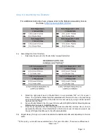
Page 2: ... make sure that you have identified the various parts Hardware for different surface applications Prior to assembly please take a moment to understand the type of mounting surface you are working with There are a variety of installation surfaces as shown in the table below Given the wide variety of mounting surfaces please be aware that Awntech does not supply mounting hardware You will need to pu...

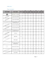
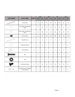
Page 3: ...Page 3 Parts List Parts Included ...

Page 4: ...Page 4 ...

Page 5: ...r to the other of the same g Aluminum Bar Connector by using a rubber mallet and gentle tapping the angled end of the b2 Top Bar iv Install 8 L Sheet Screws on the Full Top Bar Figure A1 1 b3 Full Top Bar Assembly 1b c3 Full Top Bar Assembly Refer to Figure A1 2 i Gather your 1 c1 Front Bar 1 c2 Front Bar 1 g Aluminum Bar Connector and 8 L Sheet Screws ii Insert of the g Aluminum Bar Connector ins...

Page 6: ...when installed Refer to Figure A2 1 Back of the Awning ii Insert a Black Nylon L connectors into the ends of the b3 Full Top Bar iii Connect the d1 Left Frame and d2 Right Frame ends to the b3 Full Top Bar by using a rubber mallet hammer iv Install 2 L Sheet Screws on both corners of the frame to secure d1 d2 and b3 to the a Black Nylon L Connectors Refer to Figure A2 2 Figure A2 1 Positioning the...

Page 7: ... top of 3 f Middle Support Connectors to the 3 pre drilled holes on the inside of the b3 Full Top Bar with 3 L Sheet Screws ii Lay out the 1 e2 Center Middle Support and place the 2 e Middle Supports on either side of the e2 Center Middle Support The e2 Center Middle Support will have 4 pre drilled holes When installing face the pre drilled holes towards the backside of the awning and furthest awa...

Page 8: ...ts don t connect easily try using a rubber mallet to tap them into the slits iii Secure Shutter Slates to the h Louver l Frame with k Right Shutter Slat Mounting Braces Refer to A4 2 on how to install the braces iv Once the k Right Shutter Slat Mounting braces are attached continue step ii iii to assemble the left side of the Shutter Slats to the 2nd h Louver l Frame be sure to use the j Left Shut...

Page 9: ...sert the U Shape part of the k right Shutter Slat Mounting Braces directly into the right side slit that is between the h Louver l Frame and the i Shutter Slats The U Shape should lay flat against the h Louver l Frame when inserting it in and that the braces are installed in the same direction 3 Once inserted push down the extenders of the k Left Shutter Slat Mounting Braces so that they are lying...

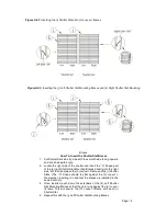
Page 10: ...oriented so that the b Top Bar is furthest from you ii Ensure that the first Shutter Set is oriented where the slats point downwards towards you iii Place the Shutter or slide it upwards in between the grooves of the Middle Supports and the Left and Right Frames iv Repeat the same steps for each shutter Figure A5 1 Inserting Shutters into Frame ...

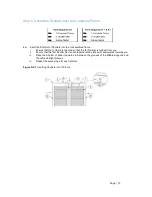
Page 11: ... the c3 Full Front Bar to the d1 and d2 Left and Right Frame with a Rubber Mallet iv The f Middle Support connector should attach to the middle support Be sure the pre drilled holes on the tongs on the f Middle Support are aligned with the pre drilled holes on the e Middle Support ends and e2 Center Middle Support ends for 6 8ft widths v Install the l Sheet Screws into the pre drilled holes locate...

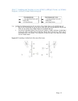
Page 12: ...h each other and also between the grooves of the d1 and d2 Left and Right Frame and e Middle Support ii Locate the 6 pre drilled holes on the h Louver l Frame on each shutter set Install sheet screws into each pre drilled hole to install the Shutter sets to the awning There are no pre drilled holes on the inside of the frame More force will need to be used when drilling into the frames metal Figur...

Page 13: ...ws into each hole to fasten the n Frame Wall Brackets iv Attach one side of the m Projection Arms to the larger holes on the installed n Frame Wall Bracket Feed the r Bolt through the holes and tighten it with the t nut 8b Repeat steps i through iv for the other m Projection arms i Install the last two n Frame Wall Brackets to the ends of the m Projection Arms ii Line up the hole at the end of 1 m...

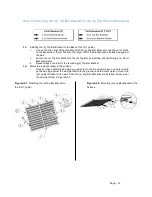
Page 14: ...the b Top Bar by inserting and tightening 2 x Short Bracket Screws iii Repeat steps a and b for the remaining q Top Bar Bracket 9b Mount the top bar bracket to the surface i Once you have determined where you want to mount the awning have one person hold up the awning against the wall parallel with the ground and the other person mount the q Top Bar Bracket to the wall Once the q Top Bar Brackets ...

Page 15: ...rms are attached plate of the n Wall Bracket against your surface and mount it with the specified hardware for your surface Refer to Figure A10 Figure A10 1 Install the n Wall Bracket to the m Projection Arms and to the Wall Step 11 Your Finished Bahama Awning Figure A11 1 Final Installation ...

Page 16: ...BILITY UNDER THIS WARRANTY The purchaser agrees and acknowledges that this Warranty agreement constitutes an executor contract The purchaser must use care in installation maintenance operation use and storage of the product in accordance with the instructions contained in the owner s manual ANY FAILURE TO INSTALL MAINTAIN OPERATE USE AND STORE THE PRODUCT IN ACCORDANCE WITH THE INSTRUCTIONS CONTAI...

Page 17: ...y of the purchaser to liberally apply touchup paint to any identified areas during their inspection for scratches or exposed metal Ignoring scratches or exposed metal will allow for corrosion or rust in the afflicted areas H GENERAL PROVISIONS AND LIMITATIONS The warranty granted herein is the exclusive remedy for the purchaser Awntech Corporation makes no other warranties to the purchaser express...

Page 18: ...casionally occurs during shipping Scrapes dents and rips in the outer packaging that could indicate possible damage should be described to the carrier at the time of delivery If damage to the product seems apparent the shipment should be refused RETURNS ORDER EXCEPTIONS Phone 817 354 9600 Fax 817 354 9612 E mail warranty awntech com TO ACQUIRE A RETURN OR REPAIR AUTHORIZATION NUMBER YOU MUST GO TH...

Reviews: