background image

15 

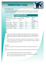
9.3 Cable Diameter Sizes: 

To select the appropriate cables gauge, measure the distance between the turbine and the batter-
ies. Make sure to include the height of the tower. Please refer to the following wire gauge chart. 


NOTES:


 

For the connection between the DPDT switch and the battery bank, you can use the same 
double wiring per polarity as in the table. Alternatively you can use a single cable AWG #6. In 
all the cases the cable between the DPDT and the battery bank has to be no more than 3ft 
long. 

 

The DPDT blade switch included in the kit allows cables up to AWG #4 easily. For the AWG #2, 
perhaps you need to remove some of the wires at the end of the cable to reduce its diameter 
or use a proper spade or pin crimp terminal. 


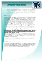
9.4 Inverters 

This device is used to convert the DC power from the battery to the standard AC power used at 
home. 

Verify the capacity and type of your inverter to ensure that it is appropriate for the load you are us-
ing. 

 

Always use 48VDC inverters (24V system need to match 24V inverters). 

 

Always use inverters equipped with battery (DC Input) overvoltage protection circuit and 
batter low voltage (under voltage) disconnect feature. 

Distance between 
the turbine and the 
DPDT switch 

Cross  
Sectional Area 

Diameter of 
the cooper 
core 

AWG # 

Maximum  
Total  
resistance 
(round & trip) 

Up to 7m (23ft) 

5.5mm

2


2.64mm 

10  

0.022Ω 

Up to 15m (49ft) 

8.0mm

2


3.19mm 

0.03Ω 

Up to 30.5m (100ft)  21mm

2


5.19mm 

0.024Ω 

Up to 46m (150ft) 

34mm

2


6.6mm 

0.023Ω 

Summary of Contents for AWS2000

Page 1: ...Your best solution for all your power needs www australianwindandsolar com AUSTRALIAN WIND AND SOLAR AWS2000 WIND TURBINE INSTRUCTION MANUAL...

Page 2: ...to the wind genera tor to the battery 7 3 D P D T Double pole double throw blade switch 7 4 Connecting the wind generator output cable extension 7 5 Connection example 7 6 Connecting the system 8 Expl...

Page 3: ...3 1 Getting Started 2 Safety instruction...

Page 4: ...se the product in the manner indicated by may depending on circumstances also have severe consequences All of the symbols described above indicate important safety information Obey all safety informat...

Page 5: ...5 3 Installation siting...

Page 6: ...in Yaw Control Free yaw 360 degrees Direction Control Swing tail Over Wind Control Stall control 600rpm mode Start up Wind Speed 3m s 11KPH 6 7MPH Cut out Wind Speed 20m s 72KPH 45MPH Survival Wind S...

Page 7: ...7 6 Assembling module 6 1 Verify the following upon purchase Tail Unit The body Unit and the tail is packed in the same box Optional parts Remote Monitor System...

Page 8: ...8...

Page 9: ...9...

Page 10: ...10 7 Connecting the System 7 1 Before connecting...

Page 11: ...11 7 5 Connection example...

Page 12: ...12 7 6 Connecting the System...

Page 13: ...ion Flashing green Generating power at con trolled rpm Wind speed range 12 20m s 43 72KPH 27 45MPH The rpm is limited to 1000 Normal Operation Flashing red Generating power at con trolled 600rpm Wind...

Page 14: ...ank depends on its capacity in Ah the average consumption cur rent of the loads and the average power supplied by the turbine This average power depends on the average wind speed condition in MPH at y...

Page 15: ...e of the wires at the end of the cable to reduce its diameter or use a proper spade or pin crimp terminal 9 4 Inverters This device is used to convert the DC power from the battery to the standard AC...

Page 16: ...16...
Page 17: ...ion When strong winds blow tree branches and other objects may make contact with and damage the wind turbine its support pole or its wiring Continued use of the wind turbine when it is damaged may cau...

Page 18: ...be replaced Insufficient charging current to the battery bank when the rotor is run ning Consistent air turbulence condition 1 Change the location and or increase the height of the tower mast Make su...

Page 19: ...DPDT switch is not in The rotor remains stopped even with high wind speed conditions If the indicator light is off There is some mechanical problem rotor shaft bearings hub internal stator and rotor...

Page 20: ...system 28 6V Battery bank capacity in Ah lower than the recommended absolute minimum of 420Ah The battery bank voltage increases easily and fast forcing the unit to activate the controlled rpm mode an...

Page 21: ...ber Installation Date Installation Location Other Requirements Send at least three photos of the working wind turbine Warranty Service Card Client Name Model Number Installation Date Phone Number Appl...

Reviews: