background image

19 

The turbine (especially its tail) is 
yawing continuously 

Swirling air because of turbulence 

Change the location and/or in-
crease the height of the tower/

Every time the rotor shaft begins to 
spin, it stops suddenly with a strong 
brake action 

Open circuit in the DC connection 
between the turbine and the 
battery bank 

Check for loose or open connec-
tions in the cables. Make sure the 
DPDT blade switch is in the ON po-
sition (neither the open not the 
brake [short circuit] one) 

The rotor remains stopped even 
with high wind speed conditions 

If the indicator light is solid red 

The battery bank voltage and/or 
the internal temperature of the 
turbine have reached their highest 
(cut-out) limit and the turbine 
stops. The turbine will resume nor-
mal operation in an automatic and 
unattended way. Wait for the prop-
er cut-in threshold or reset the unit 
disconnecting and reconnecting the 
battery voltage with the DPDT 

The rotor remains stopped even 

If the indicator light is off 

Make sure the DPDT switch is not in 

The rotor remains stopped even 
with high wind speed conditions 

If the indicator light is off 

There is some mechanical problem 
(rotor shaft bearings, hub, internal 
stator and rotor contact, internal 
damage). The unit has to be in-
spected 

The turbine works at controlled 
rpm often, with the battery bank 
voltage below the normal maxi-
mum of 57.2V (24V system 28.6V) 

The indicator light status is flashing 
red 

Normal if within the + 7% of toler-
ance in the battery voltage thresh-
old values shown in the Operating 
Status Table 

The turbine works at controlled 
rpm often, with the battery bank 
voltage below the normal maxi-
mum of 57.2V (24V system 28.6V) 

The indicator light status is flashing 
red 

Excessive voltage drop through the 
cables and/or related connectors. 
Please check the proper cable 
gauge vs length as per the cable 
gauge chart, the related connectors 
and the batteries’ posts 

The turbine works at controlled 
rpm often, with the battery bank 
voltage below the normal maxi-
mum of 57.2V (24V system 28.6V) 

The indicator light status is flashing 
red 

High resistance or loose connection 
in the turbine’s brushes and/or 
their tracks. They should be in-
spected and cleaned 

Summary of Contents for AWS2000

Page 1: ...Your best solution for all your power needs www australianwindandsolar com AUSTRALIAN WIND AND SOLAR AWS2000 WIND TURBINE INSTRUCTION MANUAL...

Page 2: ...to the wind genera tor to the battery 7 3 D P D T Double pole double throw blade switch 7 4 Connecting the wind generator output cable extension 7 5 Connection example 7 6 Connecting the system 8 Expl...

Page 3: ...3 1 Getting Started 2 Safety instruction...

Page 4: ...se the product in the manner indicated by may depending on circumstances also have severe consequences All of the symbols described above indicate important safety information Obey all safety informat...

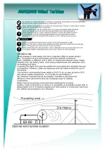
Page 5: ...5 3 Installation siting...

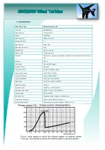
Page 6: ...in Yaw Control Free yaw 360 degrees Direction Control Swing tail Over Wind Control Stall control 600rpm mode Start up Wind Speed 3m s 11KPH 6 7MPH Cut out Wind Speed 20m s 72KPH 45MPH Survival Wind S...

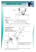
Page 7: ...7 6 Assembling module 6 1 Verify the following upon purchase Tail Unit The body Unit and the tail is packed in the same box Optional parts Remote Monitor System...

Page 8: ...8...

Page 9: ...9...

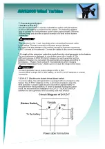
Page 10: ...10 7 Connecting the System 7 1 Before connecting...

Page 11: ...11 7 5 Connection example...

Page 12: ...12 7 6 Connecting the System...

Page 13: ...ion Flashing green Generating power at con trolled rpm Wind speed range 12 20m s 43 72KPH 27 45MPH The rpm is limited to 1000 Normal Operation Flashing red Generating power at con trolled 600rpm Wind...

Page 14: ...ank depends on its capacity in Ah the average consumption cur rent of the loads and the average power supplied by the turbine This average power depends on the average wind speed condition in MPH at y...

Page 15: ...e of the wires at the end of the cable to reduce its diameter or use a proper spade or pin crimp terminal 9 4 Inverters This device is used to convert the DC power from the battery to the standard AC...

Page 16: ...16...
Page 17: ...ion When strong winds blow tree branches and other objects may make contact with and damage the wind turbine its support pole or its wiring Continued use of the wind turbine when it is damaged may cau...

Page 18: ...be replaced Insufficient charging current to the battery bank when the rotor is run ning Consistent air turbulence condition 1 Change the location and or increase the height of the tower mast Make su...

Page 19: ...DPDT switch is not in The rotor remains stopped even with high wind speed conditions If the indicator light is off There is some mechanical problem rotor shaft bearings hub internal stator and rotor...

Page 20: ...system 28 6V Battery bank capacity in Ah lower than the recommended absolute minimum of 420Ah The battery bank voltage increases easily and fast forcing the unit to activate the controlled rpm mode an...

Page 21: ...ber Installation Date Installation Location Other Requirements Send at least three photos of the working wind turbine Warranty Service Card Client Name Model Number Installation Date Phone Number Appl...

Reviews: