Oxygen 5 Digital - User Manual
Version 2.5 - 12/22/2010
Axel Technology srl
www.axeltechnology.com
|
List Of Tables
101
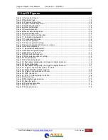
12 List Of Tables
Table 8-1: Frame clock input BNC.................................................................................................79
Table 8-2: Frame clock output BNC...............................................................................................79
Table 8-3: VGA 15p D-Sub connector............................................................................................79
Table 8-4: Keyboard & Mouse mini DIN connector .........................................................................79
Table 8-5: USB connector (2x) ......................................................................................................79
Table 8-6: RS232 9pin SUB-D connector.......................................................................................80
Table 8-7: Ethernet RJ45 connection.............................................................................................80
Table 9-1: MIC RJ45 connection ...................................................................................................81
Table 9-2: Line input RJ45 connection ...........................................................................................82
Table 9-3: Digital input/output RJ45 connection..............................................................................83
Table 9-4: Line output RJ45 connection.........................................................................................84
Table 9-5: CRM output RJ45 connection (A&B)..............................................................................85
Table 9-6: Phones RJ45 connection (C&D)....................................................................................85
Table 9-7: CobraNet RJ45 (Ethernet) connection. ..........................................................................86
Table 10-1: MIC patch panel XLR wiring ........................................................................................94
Table 10-2: Phones patch panel jack wiring ...................................................................................94
Table 10-3: Line I/O patch panel XLR wiring ..................................................................................95
Table 10-4: Standard RJ45 wiring .................................................................................................95
Table 10-5: RJ45 pinning in GPIO-TLL mode .................................................................................95
Table 10-6: RJ45 pinning in GPO-Relay mode ...............................................................................96


