Oxygen 5 Digital - User Manual
Version 2.5 - 12/22/2010
Axel Technology srl
www.axeltechnology.com
|
Available I/O rac k
cards
85
8.5 CRM output card
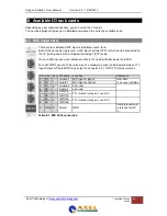
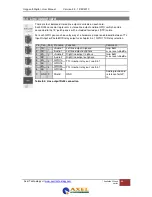
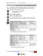
There are four stereo outputs available on this card. RJ45 connector A&B represents the
CRM stereo line output. RJ45 connector C&D represents the stereo phones outputs.
Each RJ45 connector has also two GPIO’s which can be connected to the 19” patch
panels with a shielded twisted pair (STP) cable.
This stereo output card has some special functions:
-
Analog level and mute functionality.
-
Headphone amplifiers.
RJ45 A is stereo balanced output 1
RJ45 B is stereo balanced output 2
RJ45 C is stereo headphone output 3&4
RJ45 D is stereo headphone output 3&4
For each GPIO you can choose, by way of a hardware jumper on de board, between TTL
Input/Output or Photo-MOS relay output see chapter 9.3.1 GPIO TTL/Relay selection
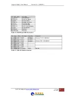
Table 8-5: CRM output RJ45 connection (A&B)
Table 8-6: Phones RJ45 connection (C&D)
Pin Con. Pair Pin name Function
Comment
1
1A
1
+Audio 1 Left line output in-phase
Imp. 56
Ω
max. level +20dBu
2
1B
-Audio 1
Left line output out-phase
3
2A
2
+Audio 2 Right line output in-phase
Imp. 56
Ω
max. level +20dBu
6
2B
-Audio 2
Right line output out-phase
5
3A
3
GPIO1a
TTL in/out or relay out, see 9.3.1
4
3B
GPIO1b
7
4A
4
GPIO2a
TTL in/out or relay out, see 9.3.1
8
4B
GPIO2b
S GND S
Shield
GND
Audio ground and
reference for GP-
In
Pin Con. Pair Pin name Function
Comment
1
1A
1
+Audio 1 Left phones 1 output
Imp. 5
Ω
minimal phones
imp. 32
Ω
2
1B
-Audio 1
Right phones 1 output
3
2A
2
+Audio 2 Left phones 2 output
Imp. 5
Ω
minimal phones
imp. 32
Ω
6
2B
-Audio 2
Right phones 2 output
5
3A
3
GPIO1a
TTL in/out or relay out, see 9.3.1
4
3B
GPIO1b
7
4A
4
GPIO2a
TTL in/out or relay out, see 9.3.1
8
4B
GPIO2b
S GND S
Shield
GND
Audio ground and
reference for GP-
In


