Oxygen 5 Digital - User Manual
Version 2.5 - 12/22/2010
Axel Technology srl
www.axeltechnology.com
|
Patch panels
95
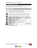
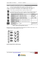
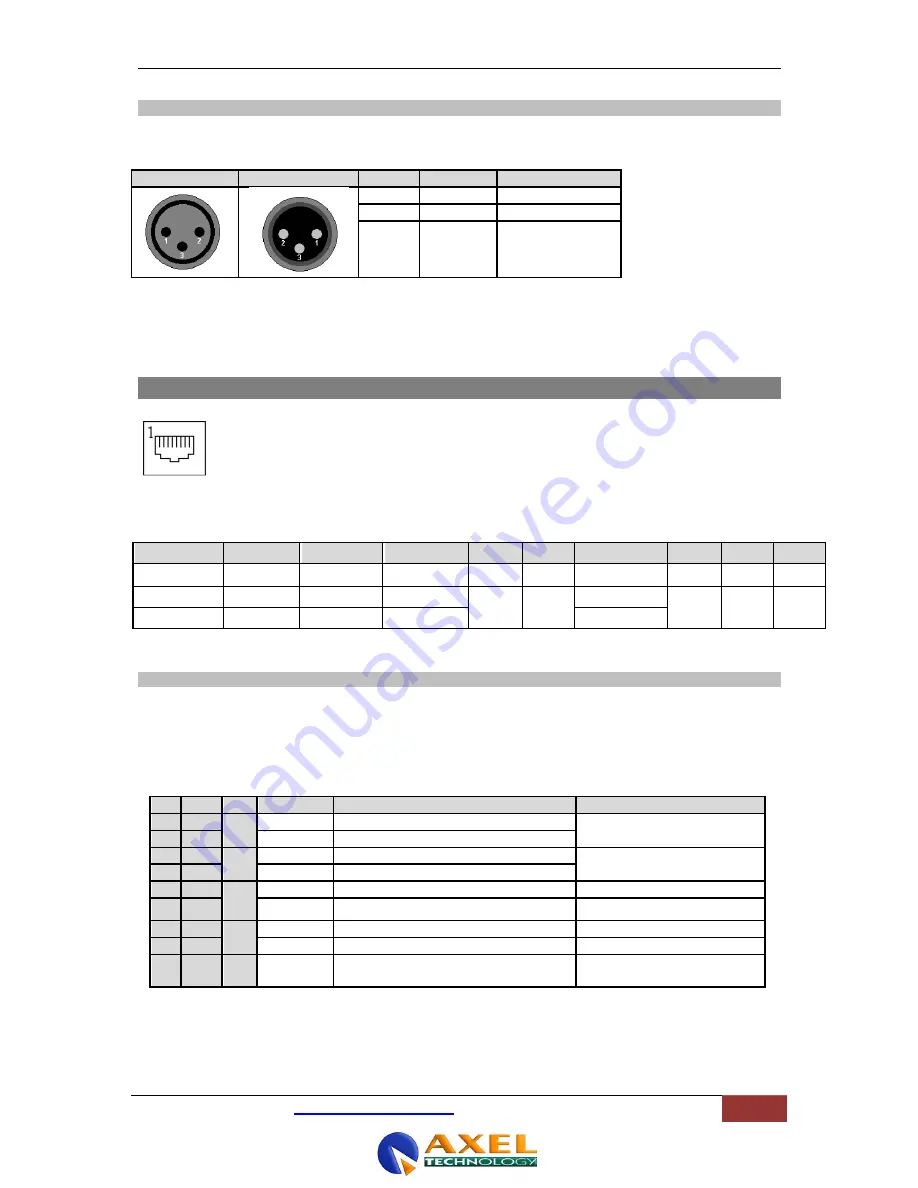
9.2.4 Stereo line input and output
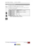
The line I/O jack patch panel houses female jack connecters, the line I/O XLR patch panel houses
XLR type connectors (male or female).
Female XLR
Male XLR
Name
Function
Pinning
2
+Audio
Audio in phase
3
-Audio
Audio out phase
1
Shield
Ground
Table 9-3: Line I/O patch panel XLR w iring
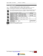
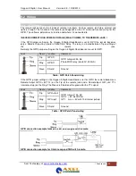
9.3 Standard RJ45 wiring
Figure 30: RJ45 Connector
Pin 1
Pin 2
Pin 3
Pin 4 Pin 5
Pin 6
Pin 7 Pin 8 Shield
RJ45 name
1A
1B
2A
3B
3A
2B
4A
4B
S
Ball
Left (Hot) Left (Cold) Right (Hot)
GPIO1 GPIO1
Right (Cold)
GPIO2 GPIO2 Shield
Phones
Left 1
Right 1
Left 2
Right 2
Table 9-4: Standard RJ45 w iring
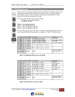
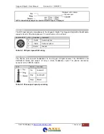
9.3.1 GPIO TTL/Relay selection
Each RJ45 connection on I/O cards handles audio signals and GPIOs.
The GPIO pins can be configured to work as:
•
TTL in and out
this is selected by GPIO1 jumpers in the place 12 and GPIO2 jumpers in place 45. These
jumpers are located on the I/O cards, close to the RJ45 connectors.
Table 9-5: RJ45 pinning in GPIO-TLL mode
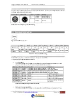
•
Relay out (no input available).
this is selected by GPIO1 jumpers in the place 23 and GPIO2 jumpers in place 56. These
Pin Con. Pair Pin name Function
Comment
1
1A
1
+Audio 1 Left audio input or output in-phase
Imp. 2k Ohm
max. level +20dBu
2
1B
-Audio 1
Left audio input or output out-phase
3
2A
2
+Audio 2 Right audio input or output in-phase Imp. 2k Ohm
max. level +20dBu
6
2B
-Audio 2
Right audio input or output out-phase
5
3A
3
GPIO1a
GP-Out
+5V TTL out, 560R
4
3B
GPIO1b
GP-In
+5V TTL in, 10kR int. pull-up
7
4A
4
GPIO2a
GP-Out
+5V TTL out, 560R
8
4B
GPIO2b
GP-In.
+5V TTL in, 10kR int. pull-up
S
GND S
Shield
GND
Audio ground and reference
for GP-In

