Oxygen 5 Digital - User Manual
Version 2.5 - 12/22/2010
Axel Technology srl
www.axeltechnology.com
|
Patch panels
96
jumpers are located on the I/O cards, close to the RJ45 connectors.
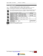
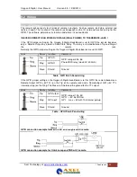
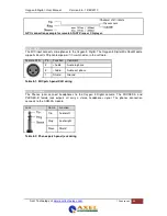
Table 9-6: RJ45 pinning in GPO-Relay mode
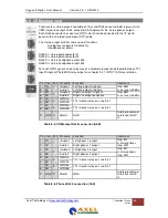
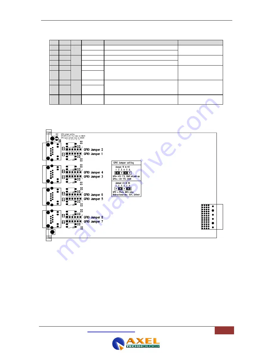
The figure shows how the jumper selection on the I/O card looks:
Figure 31: GPIO TTL/Relay j umper selection
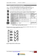
Pin Con. Pair Pin name Function
Comment
1
1A
1
+Audio 1 Left audio input or output in-phase
specifications
depends on I/O card
2
1B
-Audio 1
Left audio input or output out-phase
3
2A
2
+Audio 2 Right audio input or output in-phase
specifications
depends on I/O card
6
2B
-Audio 2
Right audio input or output out-phase
5
3A
3
GPIO1a
Relay, connecting a&b
Photo MOS relay
Bidirectional Max.
50V, 200mA
4
3B
GPIO1b
7
4A
4
GPIO2a
Relay, connecting a&b
Photo MOS relay
Bidirectional Max.
50V, 200mA
8
4B
GPIO2b
S
GND S
Shield
GND
Audio ground and
reference for GP-In


