27
ENGF-107 REV. A 01/11
© 2011 AXEON Water Technologies
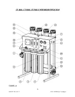
PRE-FILTER PRESSURE GAUGES
These gauges measure the feed water pressure when it enters and exits the pre-filters.
A pressure differential of 10 - 15 psi or more on the two pressure gauges indicates that
the pre-filters require servicing. For example, if the inlet pressure is 40 psi, the filter
should be changed when the outlet pressure is 30 psi or below.
PERMEATE (PRODUCT) FLOW METER & CONCENTRATE (WASTE) FLOW METER
These flow meters indicate the flow rates of the permeate and concentrate water. The
measurements, when added together, also indicate the feed water flow rate or (total
flow rate); if the system is not equipped with a concentrate recycle valve.
CAUTION: EXCESSIVE RECYCLING MAY CAUSE PREMATURE FOULING
OR SCALING OF THE MEMBRANE ELEMENTS.
LOW PRESSURE SWITCH
The low pressure switch shuts off the system when the feed water pressure drops
below 15 PSI, preventing damage to the pump. The system restarts automatically when
there is a constant pressure of 35 PSI or more.
If you notice the pressure fluctuating, and the system cycling off and on,
turn the system off and ensure that proper feed flow and pressure are available to
the system.
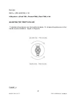
PUMP THROTTLE VALVE
This valve is installed as a standard feature on the CT-Series reverse osmosis systems.
It provides an adjustment for pump pressure, which will vary as the required system
pressure changes. As the feed water temperature decreases, and/or the feed water
TDS increases, the system will require a higher operating pressure to produce the
specified permeate flow. CT system installed in Florida may provide the specified
permeate flow of 2.77 gpm at 100 psi; however the same system installed in Maine –
much colder feed water – may require 150 psi to produce the same amount of
permeate.
Never exceed 150 psi
.
Summary of Contents for CT-4000
Page 1: ...Reverse Osmosis User s Manual Model CT 4000 CT 5000 CT 7000 CT 7000 Pictured...
Page 2: ...2 ENGF 107 REV A 01 11 2011 AXEON Water Technologies This Page Left Blank...
Page 10: ...10 ENGF 107 REV A 01 11 2011 AXEON Water Technologies HF1 STANDARD...
Page 11: ...11 ENGF 107 REV A 01 11 2011 AXEON Water Technologies HF4 OPTIONAL...
Page 12: ...12 ENGF 107 REV A 01 11 2011 AXEON Water Technologies HF5 OPTIONAL...
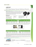
Page 13: ...13 ENGF 107 REV A 01 11 2011 AXEON Water Technologies NF3 OPTIONAL...
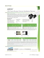
Page 14: ...14 ENGF 107 REV A 01 11 2011 AXEON Water Technologies NF4 OPTIONAL...
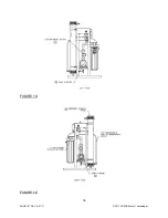
Page 17: ...17 ENGF 107 REV A 01 11 2011 AXEON Water Technologies FIGURE 1B FIGURE 1C...
Page 18: ...18 ENGF 107 REV A 01 11 2011 AXEON Water Technologies FIGURE 1D FIGURE 1E...
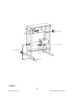
Page 39: ...39 ENGF 107 REV A 01 11 2011 AXEON Water Technologies DRAWINGS FIGURE 5...
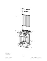
Page 40: ...40 ENGF 107 REV A 01 11 2011 AXEON Water Technologies FIGURE 6...
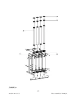
Page 41: ...41 ENGF 107 REV A 01 11 2011 AXEON Water Technologies FIGURE 7...
Page 42: ...42 ENGF 107 REV A 01 11 2011 AXEON Water Technologies FIGURE 8...
Page 47: ...47 ENGF 107 REV A 01 11 2011 AXEON Water Technologies CT 4000 FLOW DIAGRAM...
Page 48: ...48 ENGF 107 REV A 01 11 2011 AXEON Water Technologies CT 5000 FLOW DIAGRAM...
Page 49: ...49 ENGF 107 REV A 01 11 2011 AXEON Water Technologies CT 7000 FLOW DIAGRAM...
Page 54: ...54 ENGF 107 REV A 01 11 2011 AXEON Water Technologies...

