background image

PRODUCT DESCRIPTION

5

BEFORE DRIVE UNIT INSTALLATION

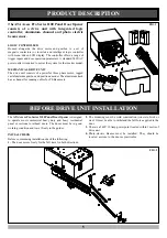
The ATA Axess Pro Series 1100 Panel Door Opener
consists of a drive unit with integrated logic 
controller, aluminium channel and photo electric
beam sensor.

LOGIC CONTROLLER

Housed along-side the drive motor and gearbox is a set of 
magnetic contactors (or inverter) and intelligent logic controller
with menu driven LCD display. The controller offers a range of
trigger inputs and door operation perameters. A standard 240V AC
power outlet is required to power the system for the inverter model.

MECHANICAL DRIVE UNIT

The drive unit consists of a powerful three phase motor, rugged
cast aluminium gearbox and position encoder. The aluminium track
has a channel for running cables for PE Beams etc.

The

ATA Axess Pro Series 1100 Panel Door Opener

is designed

to operate most commercial heavy duty and heavy residential
panel or sectional overhead doors. The doors must be in good
working condition and travel freely in the guides.

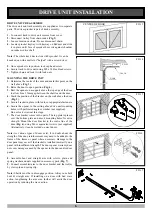
INITIAL CHECK

Before commencing installation check the following:

1.

The door moves freely for the full travel in both directions.

2.

The mounting must be solid construction (concrete, brick or
steel. It must be able to withstand the full force applied to the 
door.

3.

There is a 240V 10 Amp power point located within 1 metre of  
drive unit.

4.

Photo-electric Beams must be installed. They should be 
located  as close to the door as practicable.

FIG. 1

FIG. 2

Summary of Contents for Pro Series 1100

Page 1: ...ailure to comply will void the warranty and may cause serious personal injury and or property damage WARNING It is vital for the safety of persons to follow all instructions Failure to comply with the...

Page 2: ...TING TRAVEL LIMITS 11 SETTING PEDESTRIAN POSITION 11 CHANGING ACCELERATE DECELERATE SPEED 12 DESCRIPTION OF STANDARD OPERATION 13 MENU STRUCTURE 14 CONTROL BOARD ADJUSTMENTS 14 MENU 3 AUTO CLOSE TIMES...

Page 3: ...way is in full view at all times Make sure that remote controls are kept out of reach of children Warning It is vital for the safety of persons to follow all instructions Failure to comply with the fo...

Page 4: ...ss codes that have already been received it is able to reject unauthorised access requested attempted by thieves In addition to this each transmitter has a unique serial number so no two are alike Fur...

Page 5: ...phase motor rugged cast aluminium gearbox and position encoder The aluminium track has a channel for running cables for PE Beams etc The ATAAxess Pro Series 1100 Panel Door Opener is designed to oper...

Page 6: ...ig 5 5 Secure bracket in place with loxins or apporpriate fasteners 6 Secure the opener to the ceiling above drive unit mounting holes with perforated angle or similar not supplied Do not lock screws...

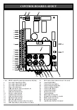
Page 7: ...terminal 14 PED N O input terminal 15 PE input jumper remove when 8 is used 16 OPN input jumper remove when 9 is used 17 STP Input Jumper remove when 10 is used 18 Console Exit Button 19 Console Prev...

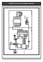
Page 8: ...E BROWN BROWN BLUE GRN YELL U1 6ET3 BROWN BLUE RED RED GRN YELL U2 FM50 201 OC BLUE BLUE BLUE BROWN FREQ J1 J2 J3 CONTROL UNIT 220V 50Hz DRIVE UNIT U4 PDE 1 04 M R S T 1 2 3 3phase 1 2HP ATA MOTOR 240...

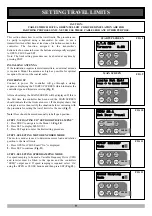
Page 9: ...ate that the limits are not set If the display shows that an input is active then rectify the situation before continuing with the procedure for setting the travel limits for the door Fig 9 Note Door...

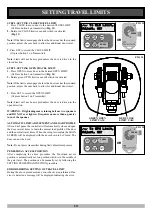
Page 10: ...additional door travel 3 Press SET to record the OPEN LIMIT Or press button 2 on Transmitter Note Limit will not be accepted unless the door is driven in the open direction WARNING If tightening cam r...

Page 11: ...PEDESTRIAN POSITION SET The controller will return to the MAIN SCREEN with the gate status shown as being in pedestrian access mode Fig 18 MENU 10 2 Set Pedestrian PRESS to Pedestrian Position SET PR...

Page 12: ...TION Activated by PED terminal with N O switch or by transmitter button with PED Function assigned The pedestrian access operation partly opens the door allow pedestrian access but prevent vehicle acc...

Page 13: ...1 Memory Reset Reload Operations See 24 Control Input Status Display See Page 23 Transmitter Testing See Page 23 Event History Display See Page 23 Memory Usage See Page 23 Periodic Service Cycle Count...

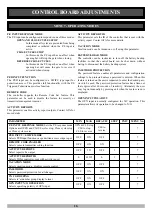
Page 14: ...As the SWP input is not available during pedestrian access the PED input can be configured to act in a SWP mode by setting the PED I P PED SWIPE MODE parameter to ON AUTO CLOSE AFTER OBSTRUCTION Two...

Page 15: ...an be programmed for both hold and pulse operation and can also be programmed to activate prior to the door motor starting The operation of the lock can be programmed to behave differently on open cyc...

Page 16: ...ontrol board can be shut down without having to disconnect the battery backup system PASSWORD PROTECTION The password feature enables all parameters and configuration settings to be protected unless a...

Page 17: ...g RELOAD DEFAULT SETTING 1 Press NEXT PREV buttons to display LOAD DEFAULT screen 2 Press SET to load the default value RETURN TO MENU If the parameter s value is not to be changed press EXIT to retur...

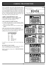
Page 18: ...ss the transmitter button you wish to use to operate the door Opener e g button 1 Fig 24 3 Press same transmitter button again as prompted by display Fig 25 STEP 3 SELECTING FUNCTION OF THE BUTTON The...

Page 19: ...to be deleted Press SET to delete or EXIT to continue editing STEP 4 EDITING THE STORE LOCATION This feature is only available when coding the first button of a new transmitter 1 Press NEXT or PREV t...

Page 20: ...and edit mode Fig 35 Used if the transmitter is not available MENU 1 Code Transmitter PRESS Press Tx er Button LIST Press Tx er Again VIEW PRESS PRESS 0 I ID D NO NAME OFF OFF OFF OFF Location Not Us...

Page 21: ...n that already contains a transmitter then the BASIC CODE TRANSMITTER PROCEDURE will be initiated and the new transmitter will replace the existing one Note that the button functions and name of the e...

Page 22: ...te its cycle 3 ACTIVATE REMOTE CODE SET MODE Using a small pin press and hold through the Coding Hole of the existing transmitter for two seconds Fig 47 4 CODE NEW TRANSMITTER BUTTON Within 10 seconds...

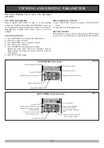
Page 23: ...l then beep each time a transmission is received If the transmitter button is stored in the controller memory and has a function assigned to it a second screen will be displayed that shows the transmi...

Page 24: ...below shows the information recorded Use the NEXT and PREV buttons to move through the list When finished viewing simply press EXIT 1 Open Cycle Time 3 Motor Encoder Mode 2 Close Cycle Time 4 Speed R...

Page 25: ...f all obstructions and persons at all times The location of the P E Beam and the manner in which it is installed might not give safety protection at all times Check to make sure that the height of the...

Page 26: ...Refer page 18 Replace battery A23 Alkaline 12V Door will not close fully Door limits positions need to be reset Reset limits positions Page 10 Door will not open fully Door limits positions need to b...

Page 27: ...PARTS LIST 27 WHEN ORDERING SPARE PARTS PLEASE QUOTE THE ORDER CODE NUMBER TO YOUR INSTALLER DISTRIBUTOR...

Page 28: ...carry out such modification or repairs m faulty or unsuitable wiring of structure to which the product is fixed or connected n radio including citizen band transmission or any electrical interference...

Reviews: