SETTING TRAVEL LIMITS
9
Motor
Encoder
Mode
O
PRESS
MENU
10.1
Set
Door
Travel
PRESS
FIG. 10
FIG. 11
This section shows how to set the travel limits. The procedure can
be partly completed using a transmitter. In order to use a
transmitter it must first have at least one of its buttons coded to the
controller. The function assigned to the transmitter's
buttons is of no concern here as the buttons are temporally assigned
to OPEN, CLOSE and SET.
Note: The limit setting procedure can be aborted at anytime by
pressing EXIT.
INSTALLING ANTENNA
If the installation requires remote transmitters, an external antenna
is required. Mount the antenna as high as possible for optimal
reception. Do not cut the coaxial cable.
POWERING UP
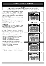
Connect to power. The controller will go through a startup
sequence displaying the STARTUP SCREEN which indicates the
controller type and firmware version (
Fig. 8
).
After a short delay the MAIN SCREEN will be displayed. If this is
the first time the controller has been used the MAIN SCREEN
should indicate that the limits are not set. If the display shows that
an input is active then rectify the situation before continuing with
the procedure for setting the travel limits for the door (
Fig. 9
).
Note:
Door should be moved manually to half open position.
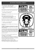
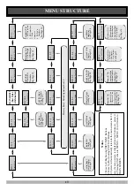
STEP 1. NAVIGATING TO “SET DOOR TRAVEL MENU”
1.
Press PREV to navigate to the Menu 10 (
Fig. 10
).
2.
Press SET to display MENU 10.1.
3.
Press SET again to enter the limit setting procedure.
STEP 2. SELECTING MOTOR ENCODER MODE
The motor encoder is used to determine motor load and relative
position to the travel limits..
1.
Press OPEN or CLOSE until “On” is displayed.
2.
Press SET to continue (
Fig. 11
).
STEP 3. SELECTING SPEED RAMPING MODE
For speed ramping to be used a Variable Frequency Drive (VFD)
and inverter must be fitted to the opener and the controllers
“FREQ” output used. If speed ramping is required select ‘On’
using the OPEN or CLOSE buttons and then press SET (
Fig. 12
).
n
PRESS
A.T.A
CB14
Firmware
#.##
STARTUP SCREEN
FIG. 8
Limits
Not
Set!
P
Pr
re
es
ss
s
<
<>
>
t
to
o
A
Ac
cc
ce
es
ss
s
M
ME
EN
NU
US
S
MAIN SCREEN
FIG. 9
CAUTION:
CABLES WHICH HAVE A GREEN/YELLOW COLOURED INSULATION ARE FOR
EARTHING PURPOSES ONLY. NEVER USE THESE CABLES FOR ANY OTHER PURPOSE.
Speed
Ramping
Mode
O
PRESS
FIG. 12
n


