2: E
le
m
en
t w
ith P
ow
er
S
ta
tio
n: S
et
up a
nd C
on
ne
ct
io
ns •
1
7
©2016 Axia Audio- Rev 1.8.1
or a cable for a “split” console configuration, please con-
tact your Axia sales representative.
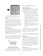
Your control surface must be connected to a Pow-
erStation MAIN using only the supplied 6-conductor
cable. Refer to Figure 2-8 in the following section.
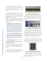
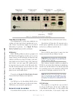
When you connected the cable to the Element as de-
scribed above, you no doubt noticed some RJ-45 con-
nectors in the vicinity. This is your CANBus distribution
hub. Do NOT connect any Ethernet cables to the CAN-
Bus distribution hub that is inside the Element. This hub
is for CANBus connections only and may cause damage
to other equipment. The RJ-45 connector is used to dis-
tribute 48 VDC to the CANBus modules and accessory
panels.
What is CANBus? Controller Area Network
(CAN) is a multicast shared serial bus standard,
originally developed in the 1980s by Robert
Bosch GmbH, for connecting electronic control
units (ECUs). Although initially created for au-
tomotive purposes, nowadays it is used in many
embedded control applications.
The CAN data link layer protocol is standardized
in ISO 11898-1 (2003).
Element with PowerStation: Setup
If you haven’t done so yet, it’s time to get your
Element out of its packing crate. This can be a two-per-
son job, so grab a partner.
Important: Like any electronic device, Element
can be affected by static electricity. Use of a
personal grounding device is strongly recom-
mended while handling the unit.
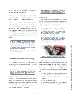
Position one person at each end of Element and,
grasping the metal enclosure at the bottom, simulta-
neously lift upward out of the shipping crate. Remove
packing materials and store them in the crate for future
use. Carefully lower Element into your counter top cut-
out, taking care to lower both sides at an equal rate to
avoid becoming jammed in the millwork.
Important: Element is a drop-in style control
surface and requires a counter top cutout. For
cutout dimensions, please refer to Appendix A.
Connections
Cable connections for Element are entirely different
from any other mixing surface you may be familiar with.
There are no audio inputs or outputs; Element needs only
a single data / power connection to operate.
Important: Your Element console MUST be
grounded. Grounding reduces the risk of elec-
tric shock by providing a “path of least resis-
tance” for electric current. Improper grounding
can result in a risk of electric shock.
Check with a qualified electrician if you are in
doubt about how to properly ground this equip-
ment. If your local electrical code prohibits the
use of a Station Ground for this purpose, as de-
scribed above, use the specific “Safety Ground”
your local regulations mandate.
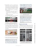
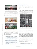
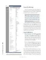
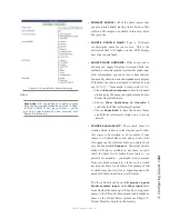
Figure 2-6: Accessing Element’s connection panel.
Element must be connected to a grounded metal
permanent wiring system or other equipment grounding
conductor using the threaded grounding stud located in-
side the connections bay. Open the bay by flipping open
the overbridge above the faders, as shown in Figure 2-7.
For ground sources, we recommend, in order of prefer-
ence:
»
“Station Ground,” the heavy copper strap found
in the walls and floors of many radio studios.
»
AC Safety Ground — the “3rd prong” of a nearby
outlet.
»
A bonded electrical conduit.
#12 AWG GREEN stranded wire is the minimum
wire gauge acceptable for grounding Element.

