2: E
le
m
en
t w
ith
Po
w
er
S
ta
tio
n: S
et
up
an
d
C
on
ne
ct
io
ns
•
1
8
©2016 Axia Audio- Rev 1.8.1
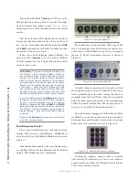
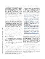
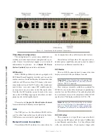
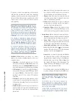
Figure 2-7: Locating the grounding stud.
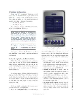
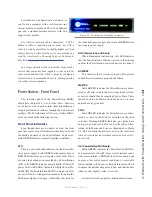
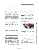
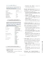
One end of the Element power / communication
cable is fitted with a strain relief. Connect this end to
the Molex connector on the back of the PowerStation
MAIN. Connect the other end to the
Molex socket on the
Element connection panel.
Figure 2-8: Detail of data/communication cable ends.
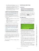
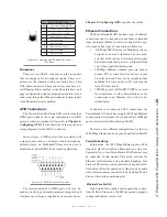
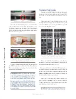
Figure 2-9: Element connection panel. Circled
connector is for power/data cable; RJ-45’s connect to
fader and accessory modules.
A DVI-D compatible monitor must be connected to
the DVI-D connector on the back of the PowerStation.
This monitor displays metering, a clock and lots of other
user interface information.
IMPORTANT: Element’s power cable is also host
to all data communication between the actual
surface and its CPU (housed in the Element Pow-
er Supply/GPIO Node) by CANBus technology; it
does not require a separate Ethernet connection.
Never connect any of the RJ-45 ports on
the Element connection panel to an Eth-
ernet switch. These ports are for connection
of Element fader and accessory modules only;
connecting them to a powered Ethernet switch
could damage the board’s electronics and void
your warranty.
“Capturing” Your Console
If you have carefully followed to steps on the preced-
ing pages, it is now time to apply power. Connect PSU1
and watch as your PowerStation and Element come to
life.
Upon power-up of your Element, some or all of
the alphanumeric displays above the faders may read
INACTIVE
. Before you can use your Element, you will
need to run the Capture routine.
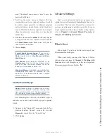
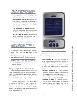
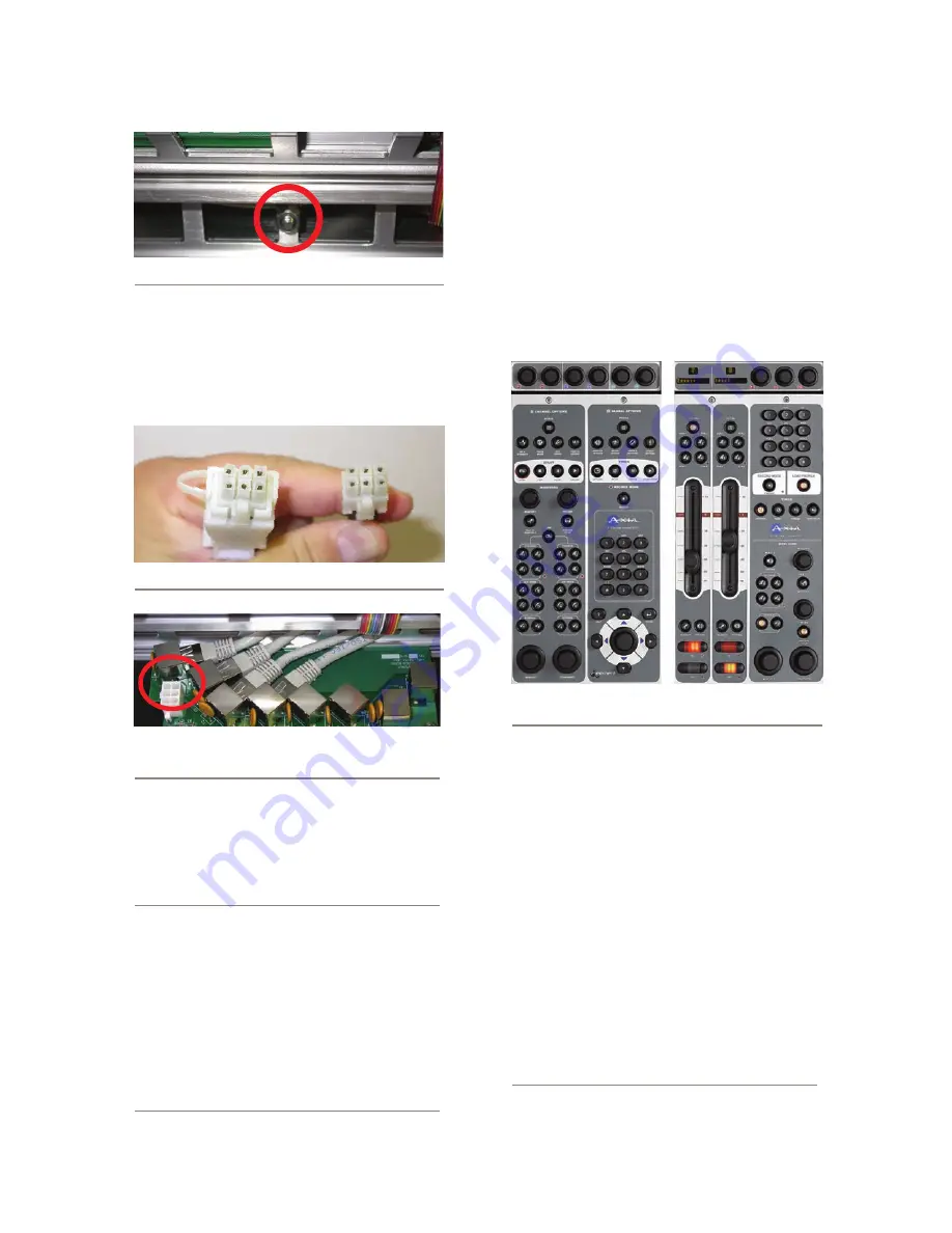
Figure 2-10: Identifying the Standard Monitor Module
(left) and M 2-Fader Module (right).
“Press and hold” the
*
and
2
keys on the Monitor
Module for 5 seconds. The alphanumeric displays above
the facers will change to read
Capture
.
Now, you will want to verify that LED displays above
the faders display the channel numbers in the order you
desire. If not, you can adjust them individually using the
PGM1
and
PGM2
buttons above each fader to change the
channel number to the one you desire.
When you’re done adjusting channel number dis-
plays, press the
8
(enter) or #
(if you have a Monitor
+2-fader module)
key to exit Capture Mode. Your Ele-
ment hardware is now ready to use.
Hello Moto: If you have motorized faders, you
can “mirror” other motorized faders while you

