5: E
le
m
en
t O
pe
ra
tio
ns •
6
0
©2016 Axia Audio- Rev 1.8.1
Element’s linear pots and associated on/off controls, al-
pha displays, bus assignment keys, etc. But “Channel” is
also used when discussing numbered Livewire network
audio streams. To avoid confusion, we’ll call Element
channel strips “Faders”.
Sources are assigned to faders for use on-air or in
production. During initial configuration, the Source
Profiles are programmed by the engineer for appropri-
ate logic and options (as outlined in previous chapters);
afterwards, whenever that source is assigned to a fader,
source logic follows.
Fader settings are instantly reconfigured whenever a
source is selected, to accommodate the unique require-
ments of the source. For example, a fader controlling a
microphone source also controls appropriate monitor
mutes. A fader controlling a line source sends “start”
and “stop” commands when the channel is turned on
and off.
Sources such as an off-air feed, can also be fed di-
rectly to the monitors for auditioning without being as-
signed to a fader.
Mix-Minus
Mix-minus setup, especially for live broadcasts, has
always been one of the most confusing aspects of run-
ning a radio console. Element makes mix-minus easy
by automating it. The operator never has to worry about
sending a source back to itself — it just can’t happen!
Several mix-minus choices – fixed and switching –
are possible, and are configured for each source when
Source Profiles are defined by the engineer (see Chapter
3 for details). Once this setup is done, no further tweak-
ing is needed; the operator simply uses the source. A Sta-
tus Symbol display on each fader tells operators when a
particular source has a mix minus output, and even tells
them which audio mix is being backfed.
Element will support as many outputs as there are
installed faders, each with its own automated mix minus
feed. Got 24 faders? You can have 24 mix-minuses!
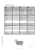
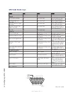
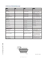
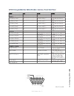
GPIO
Chapter 4 explained how sources can have associat-
ed GPIO (General Purpose Input/Output) control associ-
ated with them. Element GPIO interfaces are connected
to Element via the Livewire network, so you can locate
the actual machine connections either physically close
to source equipment or in a central equipment room.
During installation, the engineer configures sources
to accept and provide logic commands by selecting vari-
ous options. Example: studio microphones may be set up
to automatically mute the studio monitor speakers and
illuminate an on-air warning light when turned on. The
same sources can be configured to accept GPIO logic
inputs from buttons so each studio guest can have their
own
On
,
Off
,
Talk
, and
Mute
keys.
Line sources can be configured to receive start and
stop commands from the Element as well. Start/stop
messages can also be passed, via Ethernet, to a comput-
er-based playout system.
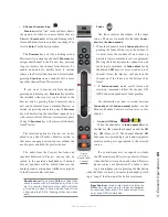
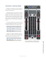
Monitor Module and SoftKnobs
The Monitor Module and SoftKnobs contain Ele-
ment’s operating controls. This is where you’ll find vol-
ume and selection controls for monitors and headphones,
as well as keys that provide fast access to show profiles,
EQ & dynamics, Aux feeds and more. There are two
different type of Monitor Modules: one that contains
only monitor and option controls, and one that has fewer
monitor controls but adds two channel faders.
Software
The Element operating system uses a high-perfor-
mance embedded Linux kernel to help ensure bullet-
proof, 24/7 operation. Software updates can be obtained
from Axia via the Internet and applied by the station en-
gineer. Axia Support recommends performing backups
or making printouts of Show Profiles and other configu-
ration data before applying new software updates.
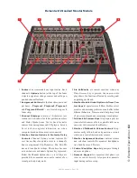
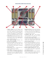
Control Callouts
On the following pages are a “bird’s-eye view” of
Element, with major controls and their functions.


