3: A
dv
an
ce
d P
ro
gr
am
m
in
g • 1
4
Version 1.2 July 2010
IC 20 and IC 1 Intercom Web Pages
All of the intercom panel’s parameters may be con-
figured using the IP-Intercom Panel’s Web configura-
tion pages. To access the Web pages from a computer,
the computer and IP-Intercom Panel must be connected
to the same LAN (or, the computer and Node can be
connected using a “crossover 10/100 Base-T” Ethernet
cable). To connect, open your web browser and enter the
IP address of the device to be configured. Your browser
should now display the device’s home page, with links to
the various functions available.
A few things to remember:
We assume you
know the basics of network architecture, but we
must mention that the first three numbers of the
IP address of the computer you are using will nor-
mally match those of the Node you are attempt-
ing to configure; i.e.,
192.168.15.xxx
. If they
don’t, the gear won’t be able to communicate
and you’ll just get frustrated.
Microsoft Internet Explorer 5 and lat-
er, and Mozilla Firefox 1.0 and later
have been tested with Axia devices.
Your browser must have the Java runtime li-
brary installed and enabled, and must al-
low “pop up” windows and display our me-
ters. To obtain the Java runtime, visit
www.java.com
.
Note that the rackmount panels will each have a
unique IP address while the Element intercom modules
share the IP address of their associated Element console
or PowerStation. The implementation of an Element IP-
Intercom module is slightly different than a standalone
Intercom panel. We will begin by looking at the web
pages for the standalone IP-Intercom panels.
The web pages for the various IP-Intercom models
are very similar. The home page of each panel gives
you access to the panel’s configuration pages. Let’s go
through these pages now starting with the Home Page.
Home Page
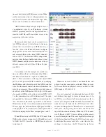
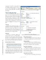
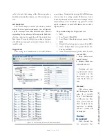
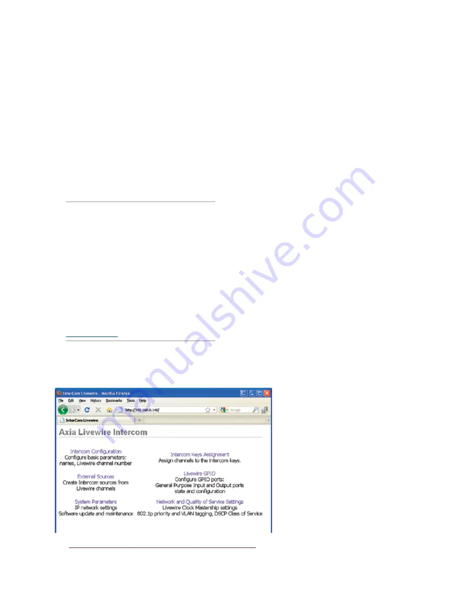
The home page shown in Figure 3-4 includes only
links to other configuration pages. As soon as you se-
lect one of these links, you will be prompted for a user
name and password. By default, the user name is
user
and there is no password.
Intercom Configuration Page
The page labelled
Intercom Configuration
is
where you configure the local input to this panel,
and assign a Livewire channel and parameters to
that source. Once configuration is complete (or at any
time in the configuration process) click on
Apply
to save
your changes to the device.
Intercom Main and Alternate Labels
Each channel label can be up to 10 characters max-
imum. An alternate label can also be entered for each
channel. The user will see the alternate la-
bel (if any) by default. A typical example
might be to use locations for the default la-
bels and user names for the alternate labels.
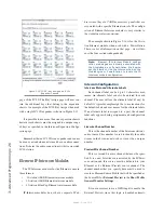
The example in Figure 3-5 shows ProdStu-
dio as the Main Label and Maciej (our bud-
dy who works there) as the Alternate label.
If an alternate label is assigned to a port, the
channel label only appears during assign-
ment and configuration functions.
Livewire Channel
This is the channel number of the Inter-
com station’s audio sources (mixed mic and
line inputs). This number is used to identify
the audio stream in the network so must be
Figure 3-4: IP-Intercom IC.20 - Home Page


