background image

EN

3

TRANSMITTER LAYOUT

Use the diagram below to familiarize yourself with the different parts of your transmitter.
The transmitter antenna is mounted internally and is located in the front portion of the transmitter. When you are driving 
your model, hold the transmitter so it is oriented as close to vertical as possible. Do not try to follow your model with 
the transmitter. This provides the best RF signal between the transmitter and the receiver. Do not cover the front of the 
transmitter during use as doing so can block the RF signal, resulting in loss of control.

Normal < > Reverse

Changes the direction of steering

Steering Dual Rate

Adjusts the total 

steering travel

Steering Trim

Adjust to make the 

vehicle drive straight 

with no input of the 

steering wheel

Battery Level Indicator

Solid Red:

 Battery voltage is good.

Flashing Red:

 Battery voltage is 

critically low (below 4V). Replace 
the transmitter batteries.

Steering Wheel

Turn right or left to 

steer the vehicle

Throttle Trigger

Pull to drive forward

Push to drive in reverse

steering wheel

Bind Button

Power Switch

Throttle Trim Knob

Adjusts the throttle control rate

Reverse

Forward

Stop

Battery Cover

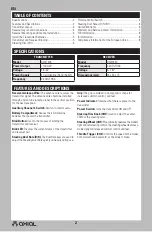
Summary of Contents for AXI31618

Page 1: ...evels of potential harm when operating this product WARNING Procedures which if not properly followed create the probability of property damage collateral damage and serious injury OR create a high pr...

Page 2: ...ed through a nylon tube antenna tube in the vertical position for the best reception Auxiliary Channel 3 Switch Switch to control servo Battery Compartment Houses the 4 AA alkaline batteries that powe...

Page 3: ...transmitter during use as doing so can block the RF signal resulting in loss of control Normal Reverse Changes the direction of steering Steering Dual Rate Adjusts the total steering travel Steering T...

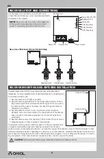
Page 4: ...am to protect it from vibration The receiver contains precision electronic parts It is the most delicate radio component on board the model and should be protected from vibration shock moisture and te...

Page 5: ...he binding process is complete the setting is remembered even when the transmitter and receiver are turned OFF This procedure generally needs to be done once Before starting the binding process connec...

Page 6: ...of Horizon exceed the individual price of the Product on which liability is asserted As Horizon has no control over use setup nal assembly modi cation or misuse no liability shall be assumed nor accep...

Page 7: ...lease include your RMA number a list of the included items and a brief summary of the problem A copy of your original sales receipt must be included for warranty consideration Be sure your name addres...

Page 8: ...oved by the party responsible for compliance could void the user s authority to operate the equipment This product contains a radio transmitter with wireless technology which has been tested and found...

Page 9: ...arks or registered trademarks of Horizon Hobby LLC All other trademarks service marks and logos are property of their respective owners Created 1 19 AXI31618 AXI31620 61064 facebook com axialinc insta...

Reviews: