Operation Instructions | EoC 20-01 | Ethernet over Coax | Master
8
2021-03-17 | Technical improvements, changes in design, printing- and other errors reserved.
2. Installation
This chapter describes the installation of the EoC 20-01.
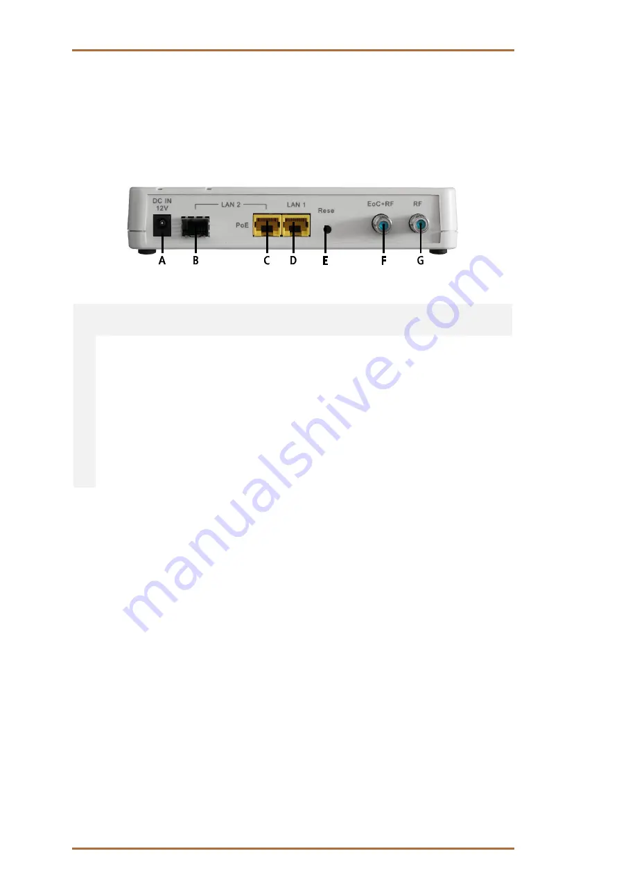
2.1. Ports on the rear panel
Port Name
Button
Type
Functions
A DC IN 12V
DC
Connect to the power adapter plug
B LAN2
(left)
SFP
Connector for 100/1000Mbps SFP transceiver
C LAN2
(right)
RJ-45
100/1000 Base-T Gigabit Ethernet port, built-in PoE
PD function.
D LAN1
RJ-45
100/1000 Base-T Gigabit Ethernet port
E Reset
–
Reset
button
F EoC+RF
F
EoC
port
G RF
F
Connect to terrestrial antenna or CATV to feed in TV
signal. Otherwise terminate with CFA 8-00
Note:
LAN2 link could be connected either at SFP or RJ45 socket.
2.2. Power supply
The DC switch on the side has two positions:
DC IN: The EoC 20-01 runs in local power mode.
Connect the power adapter to the DC IN 12V port and connect it to a wall outlet.
LINE: The EoC 20-01 runs in line power mode
Powering EoC 20-01 via the coaxial cable connected to port ‘RF+Data’ or port ‘RF’ from coax is necessary
(typical 60 VAC input (range 48V~90V, 50/60 Hz AC).
Alternatively powering EoC 20-01 via the port ‘LAN2’ Ethernet cabling (Power over Ethernet or PoE acc. to
IEEE 802.3af or 802.3at, it supports mode A and B).


