5
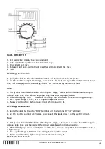
1. Apply the black test lead to “COM” jack and the red one to “V/Ω/mA” jack (Max. 200mA), or the
red one to “10A” jack(Max.10A);
2. Set the knob to a proper DCA range, and connect the leads in series to the electric circuit
under test, LCD displays polarity and current value under test connected by the red test lead
Note :
1. First, set the knob switch to the top range if you do not know the approximate value of the
measured current, and then select the appropriate range based on the displayed value.
2. If the LCD shows only "1", it means that the measuring range has been exceeded. Select a higher
range using the knob switch.
3. Max. input current is 200mA or 10A (depends on the insert position of the red test lead), over
large current will melt the fuse. When measuring, if the meter is no reading display, please check
the relevant fuse.
Resistance measurement
1. Apply the black test lead to “COM” jack and the red one to “V/Ω” jack;
2. Set the knob to a proper resistance range, and connect the leads crossly to the resistance under test.
Note :
1. The LCD displays “1”, while the resistance is over the selected range. The knob should be
adjusted to a higher range. When resistance under test is over 1MΩ, reading shall be stable in a few
seconds, which is a normal status when measuring high resistance.
2. When input terminal is in open circuit, overload displays.
3. When measuring in line resistor, be sure that the power is off and all capacitors are released
completely.
4. Do not input voltage at the range of resistance, it is forbidden absolutely.
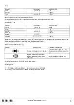
Diode and Continuity test
1. Apply the black test lead to “COM” terminal and the red one to V/Ω terminal (the polarity of red
lead is “+”) ;
2. Set the knob to“
”range, connect test leads to the diode under test, the red test lead
connect to diode positive polarity, the reading is the approx. value of diode forward volt drop.
3. Apply test leads to two points of tested circuit, if the inner buzzer sounds, the resistance is less
than (70 ± 20) Ω.
Battery test
Set the range to :1.5V” or “9V”, it can test if the “1.5V” or “9V” battery has enough
working current, thus can judge the quality of battery.
MAINTENANCE
Do not try to modify the circuit.
NOTE:
1. Do not input voltage over than DC 600V or AC 600Vrms;
2. Do not measure a voltage on range Ω;
3. Be sure to fit on the battery correctly and close the cabin before taking measurement;
4. Remove the test leads off testing points and turns off the meter before replacing battery or fuse.
BATTERY REPLACEMENT


