background image


10 


Connect the black test lead to the ground terminal of the circuit to be measured, the test probe 

to the desired test point of the circuit. 


If the level of the test point is more than or equal to 2.3±0.2V, the LCD will show 

 and the 

voltage value, meanwhile the meter will sound discontinuously. 


If the level of the test point is less than or equal to 0.8±0.2V, the LCD will show 

 and the 

voltage value, meanwhile the meter will sound continuously. 


If the probes are open, the LCD will show a TTL logic level’s approximate midvalue: 1.0~1.4V. 

Auto Power off 

If the meter is not operated for about 15 minutes, it will turn off automatically and stay in Sleep 
mode.  

To arouse the meter from Sleep, turn the function switch or press the 

 button. 

BATTERY REPLACEMENT


When the symbol 

 appears on the display, it indicates that the battery is low. To replace the 

battery, remove the screw from the battery cover, replace the exhausted battery with a new 
battery of the same type. Reinstall the battery cover and reinstall the screw. 

Note: 

Before replacing battery, set the function switch to OFF position. 

FUSE REPLACEMENT 

Fuse rarely needs replacement and is blown almost always as a result of operator’s error. The meter 
uses a fuse with specified ratings: F 250mA L 250V 

To replace the meter’s fuse: 


Set the function switch to 

OFF

 position. 


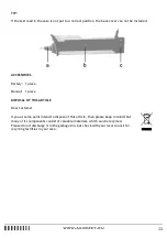
Remove the battery door (“c”) 


Remove the “a” part by turning it. 


Remove the back cover’s screws, then remove the back cover (“b”). 


Remove the fuse by gently prying one end loose, then slide the fuse out of its bracket. 


Install a new fuse of the specified ratings. 


Reinstall the back cover, battery door the “a” part and all the screws. 

Summary of Contents for AX-201

Page 1: ...Pen probe style autorange digital multimeter AX 201 Owners manual...

Page 2: ...n b Inspect the test lead for damage insulation or exposed metal Check the test lead and test probe for continuity Replace damage test lead before you use the meter c Do not use the meter if it operat...

Page 3: ...within Measurement Categories III and IV Caution To avoid possible damage to the meter or to the equipment under test follow these guidelines Disconnect circuit power and discharge all capacitors bef...

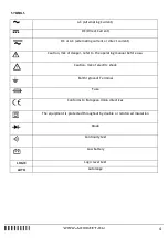
Page 4: ...tion risk of danger refer to the operating manual before use Caution risk of electric shock Earth ground Terminal Fuse Conforms to European Union directives The equipment is protected throughout by do...

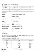
Page 5: ...Rate About 3 times sec Battery 9V 6F22 or equivalent Low Battery Indication show on the display Operating condition 0 40 C relative humidity 75 Storage condition 20 60 C relative humidity 85 Size 230...

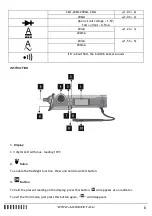
Page 6: ...the built0in buzzer sounds INSTRUCTION 1 Display 3 digits LCD with max reading 1999 2 Buton To enable the flashlight function Press and hold down this button 3 Button To hold the present reading on t...

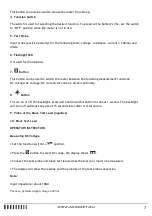
Page 7: ...tions DC voltage AC voltage DC current AC current diode continuity 8 Button To turn on or off the backlight press and hold down this button for about 1 second The backlight will turn off automatically...

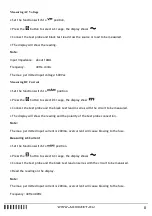
Page 8: ...he display show Connect the test probe and the black test lead in series with the circuit to be measured The display will show the reading and the polarity of the test probe connection Note The max pe...

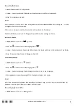
Page 9: ...he function switch to position Press the button to make the display show Connect the test probe to the anode of the diode the black test lead to the cathode of the diode Read the approximate forward v...

Page 10: ...ess the button BATTERY REPLACEMENT When the symbol appears on the display it indicates that the battery is low To replace the battery remove the screw from the battery cover replace the exhausted batt...

Page 11: ...Manual 1 piece DISPOSAL OF THIS ARTICLE Dear Customer If you at some point intend to dispose of this article then please keep in mind that many of its components consist of valuable materials which c...

Reviews: