background image

13 | 

A x i o m   T o o l   G r o u p


6-


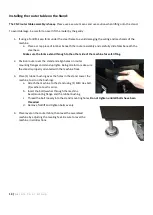
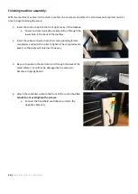
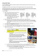
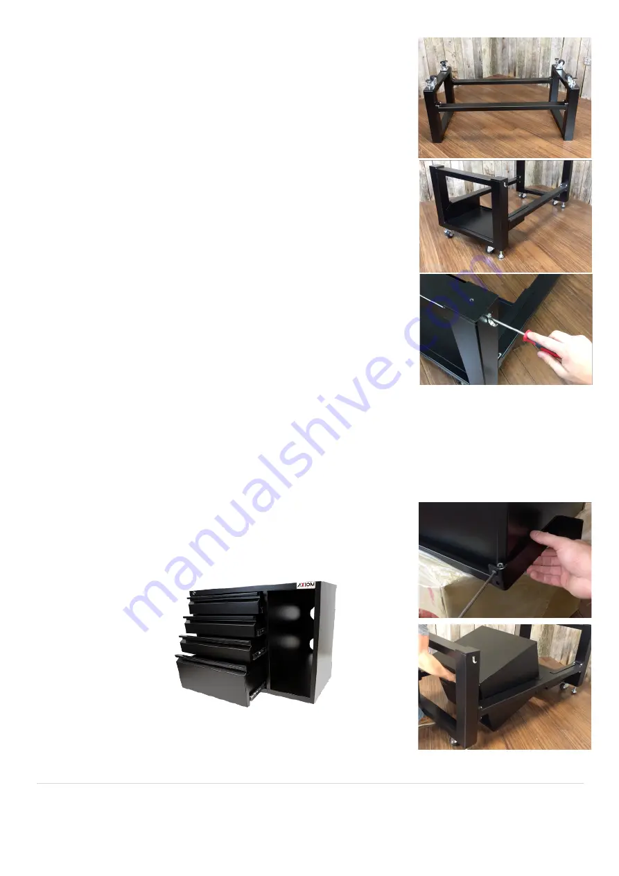
With assistance, the stand can now be flipped over onto the casters and 
leveling feet. 

7-


Flip the Shelf upside down and stick (1) of the rubber pads on each corner 
of the shelf flange. 

a.


Install shelf between the braces on the stand, all the way towards 
the rear.  

b.


The small rubber pads should now be between the flange and the 
top surface of the brace. This will help prevent unwanted movement 
and scratching.  

c.


The DSP hook for the controller should be installed on the front right 
side of the stand.  


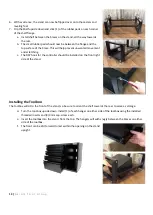
Installing the Toolbox: 

The toolbox will sit to the front of the stand, so be sure to orient the shelf towards the rear to serve as storage. 

d.


Turn the tool-box upside down. Install (1) of each hanger on either side of the toolbox using the installed 
threaded inserts and (2) 3mm cap-screw each. 

e.


Insert the toolbox into the stand, from the top. The hangers will with snugly between the braces on either 
side of the toolbox.  

f.


The front can be slid forward to rest within the opening on the stand 
upright. 


Summary of Contents for AR16 ELITE

Page 1: ...AR8 16 ELITE MANUAL Axiom Tool Group Inc All rights reserved Rev 1 2 2020 ...

Page 2: ...owledge have been obtained Your AutoRoute machine is intended for cutting wood acrylics wood fiber composites certain plastics and non ferrous metals Do not use this machine for other than its intended use If used for other purposes Axiom disclaims any real or implied warranty and holds itself harmless from any injury that may result from that use Shop Environment 1 Ensure that the floor can bear ...

Page 3: ...it breaker in accordance with local codes Install a separate circuit if necessary to limit power loss when multiple machines in your shop are operating simultaneously If necessary place a cover on the outlet to prevent accidental disconnection 17 Perform all machine adjustments or maintenance with the machine unplugged from the power source 18 Follow effective lockout procedures to reduce the risk...

Page 4: ... will do the job better and more safely 36 Do not touch a cutting tool immediately after use It will be hot and may cause skin burns Exercise caution when handling the collet and spindle nut if the cutting tool is hot Keep a heavy glove or oven mitt on hand for the purpose 37 Do not lay a hot cutting tool on its side Create a rack for cooling off hot cutting tools 38 Use recommended accessories im...

Page 5: ...cy switch need depress this button 3 Close the padlock 4 Place the KEY in a safe place out of the reach of children To lock out using the Emergency switch on the AR16 Elite 1 Depress the Emergency Stop button 2 Rotate the button counterclockwise to remove 3 Store button in safe location machine remains inoperable until unlocked 4 To unlock reinsert button and rotate clockwise until the Emergency S...

Page 6: ... 2 Operating procedure 18 8 3 HOME Position 18 8 4 Moving Router Spindle Head 19 8 5 Setting Work Origin 20 8 6 Programming Additional Origins 22 8 7 Returning to Programmed Origins 22 8 8 Setting Spindle RPM 23 8 9 Processing a File 23 8 9 1 Copying Files to internal Memory 23 8 9 2 Deleting Internal Files 24 8 9 3 Speed Scale Adjustment 24 8 9 4 Pausing During a Toolpath 24 8 9 5 Part Work 25 9 ...

Page 7: ...lectro Spindle Spindle Speed 0 24000 RPM Rapid Feed Rate 320 IPM 8 M min Precision Linear Guide Rails X Y Z Axis Precision Ball Screw X Y Z Axis Power Requirements 220V 50 60 Hz 15A Single Phase Working Table High Rigidity Interlocking Aluminum Integrated MDF Spoil Board Gantry Bridge High Rigidity Aluminum Extrusion Gantry Support Gravity Cast Aluminum Alloy Gantry Clearance 8 200mm Machine Base ...

Page 8: ...ithin a spindle nut Conventional Cut Refers to the relationship of the cutting tool rotation to the direction of feed A conventional cut deflects the toward the cut against the direction of the feed Compression Bit A cutting tool with a combination of up and down shear cutting edges Typically used for cutting laminate material to prevent tear out on both sides of the sheet Deflection Tool deflecti...

Page 9: ...m pods and others Home Position Mechanical point set using magnetic limits switches MCM Machine Constant Parameters allow manufacturer to define certain machine constants to match specifications of the equipment and machining requirements Origin User designated zero point for the work piece From which the router will reference the positioning of all cutting Plunge The distance on the Z axis that t...

Page 10: ... RPM Step Down Distance in Z axis that the cutting tool plunges into the material Step over The amount the cutting tool moves away from the previous cutting path as it routes the new path Surfacing The process of leveling the surface of the spoil boards so that they are perpendicular to the spindle Tool path User defined route which the cutter follows to machine a workpiece Touch Off Puck A device...

Page 11: ...Leveling Feet 4 hex nuts 16 Hex bolts M8x25 16 Lock washers M8 16 Flat washer M8 16 Hex bolts M6x12 16 Lock washer M6 16 Flat washer M6 1 Controller hook 2 Machine screws M4x6 4 Small rubber pads Remove all contents from shipping boxes Do not discard carton or packing material until assembly is complete Accessories commonly ship inside machine or stand packaging and can be easily overlooked Tools ...

Page 12: ...se hex nut onto each of the 4 leveling feet 2 Turn the square stand uprights upside down Do this on top of the cardboard packaging to prevent scratching a Install the 4 leveling feet and 4 swivel casters using 1 M6 hex bolt 1 M6 lock washer and 1 M6 flat washer for each caster Tighten all the caster hardware securely The leveling feet can be adjusted later b Rotate uprights so the cross brace moun...

Page 13: ...ed movement and scratching c The DSP hook for the controller should be installed on the front right side of the stand Installing the Toolbox The toolbox will sit to the front of the stand so be sure to orient the shelf towards the rear to serve as storage d Turn the tool box upside down Install 1 of each hanger on either side of the toolbox using the installed threaded inserts and 2 3mm cap screw ...

Page 14: ...afe lifting 2 Position router over the stand and align holes on router mounting flanges and stand uprights Being careful to make sure the stand is properly oriented with the machine front 3 Place 1 rubber bushing over the holes in the stand Lower the machine to sit on the bushings a Attach the machine to the stand using 1 M10 Hex bolt 1 washer at each corner b Insert the bolt washer through the ma...

Page 15: ...ower hole in the back of the toolbox 2 Insert the cable connectors into their corresponding female receptacles and twist the collar to tighten The receptacles are keyed so the plugs will only insert one way 3 Be sure to position the electrical cord through the back of the stand safely so it will not be damaged by the castors or become a tripping hazard 4 Attach the controller cable to the front of...

Page 16: ...al cord with grounding conductor and plug The plug must be used with a matching outlet that is properly installed and grounded in accordance with local codes and ordinances These plugs must not be modified if a matching outlet is need one must be installed by a qualified electrician Improper installation may result in electrical shock If grounding instructions are not completely understood or if i...

Page 17: ...ol path files Axiom_Elite_4th Required for 4th Axis machining Axiom_Elite_PVC Required for PhotoVCarve Installed into PhotoVCarve only Axiom_Elite_Drag Disables the spindle for Drag Knife Diamond Bit operations Axiom_Elite_Laser Required for the Axiom Laser Engraving accessory To load these Post Processor files VCarve or Aspire PhotoVCarve uses different instructions Open the software click File a...

Page 18: ...paths or jobs is performed either by using a USB Flash drive USB2 0 of 8GB or smaller FAT 32 or by accessing files stored in the controller internal memory 512MB Internal memory is recommended for jobs of 1 hour run time or longer and any files that will be used frequently USB flash drives should be USB2 0 8GB or smaller formatted to FAT32 The RichAuto B58 controller keypad which is seen here uses...

Page 19: ... All axis home should be selected using the REF OK ORIGIN OK button Home position is determined by a set of magnetic proximity sensors one of which can be found on each axis These sensors can be calibrated however their overall position should not change During a HOME operation the following will occur 1 First the Z axis will raise to the top of the axis travel 2 Then the X Y axes will travel simu...

Page 20: ...al button i e X Y Z A and that axis will move until the button is released a The controller will display the location of the router in relation the current Origin as it moves b During the first 0 5 sec the button is held down the machine will operate as if in step mode and move to the nearest grid at a lower speed c While in continuous mode the machine will always stop on a grid position 2 Step mo...

Page 21: ...work material or the exact center point 3 Press X Y 0 to set the Origin for the X and Y axes a This will instantly change the displayed coordinates of the X and Y axes to 0 00 4 There are several ways to set the Z 0 or Z axis Origin which may change depending on the material or router bit that is being used a Using the provided tool touch off device Which plugs into the back of the gantry on HOME ...

Page 22: ...hould only read zero along the Z axis when the bit is touching that surface NOTE When the machine is restarted a HOME operation must be done to reset that reference point However the last programmed Origin always programmed in reference to HOME is still stored in memory Simply press the OK button and the machine will return to this location Programming Additional Origins The RichAuto controller al...

Page 23: ...ss the File button located in the upper left portion of the keypad to activate the Select Work File menu a Use the Y Y buttons to scroll up or down the list b Highlight the file location and press OK to select 2 The files in that directory will then be displayed a Use the Y Y buttons to scroll up or down the list b Highlight the desired tool path mmg filetype press OK to select 3 The controller wi...

Page 24: ...use a job 1 Press the Run Pause button during operation a The machine movement will immediately stop b Spindle will remain active 2 While the machine is Paused the bit position can be adjusted in any direction a It is recommended this be done in Step mode and in Slow speed LSP 3 After making the adjustments press Run Pause to continue the file operation a The display will show a Restore Position p...

Page 25: ...ng from a stored Breakpoint would be to press the Break Work button a File must already be loaded either from UDisk or Internal memory b Press Break Work button c Prompt will give the following instructions i Press OK to resume from existing break ii Press any other key to display the break line number only d Approve speeds to begin machining if applicable Power Failures During an accidental power...

Page 26: ...ward the center of the table and use the Touch Off Device to set the Z Axis Origin at the top of the spoil boards 5 Set the RPM 18 000 RPM 6 Use the RichAuto B58 Controller to select the surfacing program from the internal SD memory Each Elite machine is loaded with the correct surfacing program for its table size with each file running both a Pocket and a Profile toolpath E8SFC mmg 24 x 48 E16SFC...

Page 27: ...610mm Y 1210mm Z 25mm Home Start Position X 0mm Y 0mm Z 20 32mm Datum Position Z Zero Top of Material XY Bottom Left Corner Clearance Z1 5 08mm Toolpaths 2 Pocket 1 Profile 1 Tool Name 1 1 25 Mortising Bit 1 1 25 Mortising Bit Time Estimate 00 16 39 00 15 42 00 00 57 Job Layout Material Setup Toolpaths Summary ...

Page 28: ... Block X 1210mm Y 1210mm Z 20mm Home Start Position X 0mm Y 0mm Z 20 32mm Datum Position Z Zero Top of Material XY Bottom Left Corner Clearance Z1 5 08mm Toolpaths 2 E16PKT E16PFL Tool Name 1 1 25 Mortising Bit 1 1 25 Mortising Bit Time Estimate 01 03 35 01 01 02 00 02 33 Job Layout Material Setup Toolpaths Summary ...

Page 29: ...FAST SLOW Switches manual movement speed F SP or L SP 6 input X Y 0 Manually sets the X Y Axis to 0 00 Programs Origin Z C 0 Manually sets the Z Axis to 0 00 Programs Origin MODE Manual movement selection Continuous Step Distance ZRN HOME Opens the HOME menu 0 input SPINDLE Spindle start stop Decimal input TOOLSET Initiates Toolset function Negative symbol input MENU Open the User Interface Menu R...

Page 30: ...and select the desired toolpath b Then access the Advanced Process menu by pressing ADVANCED c Scroll down and select Array Work d The file parameters and array settings will be displayed and operation will begin once approved Resume Work Operates much the same as using Run Pause 1 8 to display the Save Break locations For more information see Setting a Breakpoint Mirror Work Allows a job to be mi...

Page 31: ...ME position iv Back Position Will move all axes to a programmed location after the file operation is complete b Programming the Back Position can be done similarly to the Origin point Move all axes to the desired location and height i Press Menu Z 0 to set the location Highly recommended that the Z axis is raised to the highest elevation to help prevent damage as the machine travels c A specific s...

Page 32: ...e starting point 0 0 with all movements based from that location A soft limits error may occur if the limits entered cannot be supported from current location It is suggested that a test run be performed with the Z axis elevated above the material To use the Mill Plane function 1 From the Advanced Function menu select Mill Plane Then choose either Scan or Encircle a Scan performs a surfacing progr...

Page 33: ...ns i Press OK to resume from existing break ii Press any other key to display the break line number only Scale Work This feature will allow for the increase or decrease in scale existing toolpaths Origin and all other settings will remain the same Be sure that there is enough room within the machine limits to support the increase in scale To use the Scale Work option 1 Select the desired toolpath ...

Page 34: ...e parameters need restored To do this 1 Press MENU a Highlight Menu Function User Interface and press OK b Then scroll down and select System Setup c Scroll down and select Backup Data i Choose where to save the file Flash Disk or Internal Memory d The Data bak file is now created with all the current settings for use later If the controller needs to be restored and the necessary file is not avail...

Page 35: ...n appears c Select Update System d Select the location of the file Udisk or Internal memory e Select the file The update will begin automatically Once complete the controller will display a prompt indicating that the update has been successful the controller will need to be restarted to complete After restarting the machine normal operation may be resumed Normal Menu Option 1 Save the supplied fil...

Page 36: ...Specifications Chart Spindle Setup Spindle Delay Sets the time at which the spindle starts after reading the file unit microseconds Spindle State Sets the number of spindles in operation and the input output shift points Default set Home Setup Home Speed Sets speed separately for each axis when homing Default is X Y 4500 mm sec Z 1800 mm sec and A 500mm sec Home Order Sets desired sequence of axes...

Page 37: ...sh Action is set for the Pickup option This will pick up the Z axis to the safe height parameter when the file is completed G Code Setup Sets special code read configuration in G code e g M T F I J K Pro Attribute Allows for a number of controller parameters to be set for specific applications Circle Limit Default is 1000 00 Work Array Sets up array parameter including column count row count colum...

Page 38: ...on Operate File Copy File Copy files from U disk to internal memory Delete File Delete files from internal memory View File View files from either U disk or internal memory Processing Info Shows number of files successfully processed Check Process Time Shows time used for processing file s Version View Displays the current controller software information preset by manufacturer ...

Page 39: ...d Daily with machine use 1 Wipe the ball screws and prismatic guides clean and dust free 2 Apply light machine oil to ball screws and prismatic guides using a clean cloth a Move the machine through travel limits to properly disperse lubricant 3 Check cutting tool edges for chips and or dullness 4 Generally inspect the machine for any damage 5 Ensure that slots in the spoil boards are free of sawdu...

Page 40: ...ved notice the cooling pump reservoir as seen here The output from the pump is going directly into the radiator From there the fluid travels up the wire chain to the spindle then back to the pump through the return tube To flush the system removing all the old coolant and preparing for the new fluids 1 Remove the black plug from the purge valve The black collar attached to the elbow will need to b...

Page 41: ... of fluid It should not take much to flush and refill the system Ball Nut Bearing Service 500 Hour On all Elite series machines it is recommended that the ball nut bearing assembly be serviced every 500 machine hours The rolled ball screws which are found on each axis of any Axiom CNC machine feature a re circulating bearing assembly ball nut bearing which simply rides along the threaded shaft of ...

Page 42: ...he bearing assembly along the axis in both the directions while the grease is being introduced Allowing the grease to more effectively work into the assembly 6 Reposition the bearing assembly to the Axis 7 Reinsert the mounting screws leaving them slightly loose 8 Use the controller to move this Axis to the far direction placing the bearing assembly closest to the fixed end of the Axis 9 Continue ...

Page 43: ...l reservoir check for obstacles in flow path Motor stalls resulting in blown fuses or tripped circuit Motor overloaded Reduce load on motor Short circuit in motor or loose connections Inspect connections on motor for loose or shorted terminals or worn insulation Low voltage Correct low voltage conditions Incorrect fuses or circuit breakers in power line Install correct fuses or circuit breakers Ro...

Page 44: ...p Cannot set work origin on controller May be in Machine Coordinate State Press MENU 1 to revert to first working coordinate system Buttons not functioning Enter MENU System Setup Buttons Check to verify function If buttons not working replace controller Z axis fall is too fast during processing Working speed exceeds Z axis maximum speed Set to safe speed in MENU Machine Setup Max Speed Limit Loos...

Page 45: ...ne will not move after controller receives commands One axis not moving may be poor connection Connect a different axis connection to this terminal to test If it works motor driver is okay Check connections along corresponding drive and motor All axes not moving First check 50 pin cable connection to interface board Then check power supply of motor drivers Last check mechanical elements of axis sy...

Page 46: ...46 A x i o m T o o l G r o u p AR8 Elite Part List ...

Page 47: ...47 A x i o m T o o l G r o u p ...

Page 48: ...48 A x i o m T o o l G r o u p ...

Page 49: ...49 A x i o m T o o l G r o u p ...

Page 50: ...50 A x i o m T o o l G r o u p ...

Page 51: ...51 A x i o m T o o l G r o u p ...

Page 52: ...52 A x i o m T o o l G r o u p ...

Page 53: ...53 A x i o m T o o l G r o u p ...

Page 54: ...54 A x i o m T o o l G r o u p ...

Page 55: ...55 A x i o m T o o l G r o u p AR16 Elite Part List ...

Page 56: ...56 A x i o m T o o l G r o u p ...

Page 57: ...57 A x i o m T o o l G r o u p ...

Page 58: ...58 A x i o m T o o l G r o u p ...

Page 59: ...59 A x i o m T o o l G r o u p ...

Page 60: ...60 A x i o m T o o l G r o u p ...

Page 61: ...61 A x i o m T o o l G r o u p ...

Page 62: ...62 A x i o m T o o l G r o u p ...

Page 63: ...63 A x i o m T o o l G r o u p ...

Page 64: ...64 A x i o m T o o l G r o u p ...

Page 65: ...65 A x i o m T o o l G r o u p ...

Page 66: ...ess or implied as to any matter whatsoever including but not limited to warranties of merchantability and fitness for a particular purpose are excluded Components subject to wear during normal use and over time such as paint labels or decals finish and condition seals bearings spoil boards flex cabling etc are excluded from this warranty Axiom specified maintenance procedures must be adhered to in...

Page 67: ...an be downloaded from the link below https www axiomprecision com post Visit us online at www axiomprecision com Need Assistance The Axiom Precision CNC Support Team can be reached at support axiomtoolgroup com For machine and accessory orders the Axiom Precision Sales Team can be reached at sales axiomtoolgroup com Axiom Tool Group Inc 270 Broad St Westerville OH 43081 1 844 642 4902 Contact Us ...

Page 68: ...68 A x i o m T o o l G r o u p ...

Reviews: