SBC8153 Pentium All-in-One CPU Card Family User’s Manual
Jumpers and Connectors
19
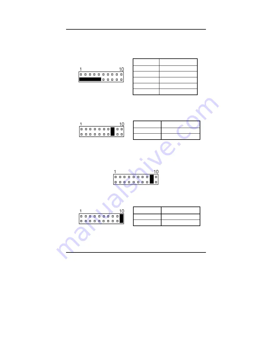
Power LED and Keylock: Pins 11 - 15
Power LED and Keylock: Pins 11 - 15
Power LED and Keylock: Pins 11 - 15
Power LED and Keylock: Pins 11 - 15
The power LED indicates the status of the main power switch. The
keylock switch, when closed, will disable the keyboard function.
J1 Pin #
Signal Name
11
Power LED
12
Reserved
13
Ground
14
Keylock
15
Ground
Turbo LED Connector: Pins 8 and 18
Turbo LED Connector: Pins 8 and 18
Turbo LED Connector: Pins 8 and 18
Turbo LED Connector: Pins 8 and 18
There is the no turbo/deturbo function on the CPU card. The Turbo
LED on the control panel will always be ON when attached to this
connector.
J1 Pin #
Signal Name
8
5V
18
Ground
Reset Switch: Pins 9 and 19
Reset Switch: Pins 9 and 19
Reset Switch: Pins 9 and 19
Reset Switch: Pins 9 and 19
The reset switch allows the user to reset the system without turning
the main power switch OFF and then ON. Orientation is not required
when making a connection to this header.
Hard Disk Drive LED Connector: Pins 10 and 20
Hard Disk Drive LED Connector: Pins 10 and 20
Hard Disk Drive LED Connector: Pins 10 and 20
Hard Disk Drive LED Connector: Pins 10 and 20
This connector connects to the hard drive activity LED on the control
panel. This LED will flash when the HDD is being accessed.
J1 Pin #
Signal Name
10
HDD Active#
20
+5V
Summary of Contents for SBC8153
Page 1: ...SBC8153 Pentium All in One PCI ISA CPU Card Family User s Manual ...
Page 12: ...SBC8153 Pentium All in One CPU Card Family User s Manual 6 ...
Page 56: ...SBC8153 Pentium All in One CPU Card Family User s Manual 50 ...
Page 60: ...SBC8153 Pentium All in One CPU Card Family User s Manual 54 ...
Page 62: ...SBC8153 Pentium All in One CPU Card Family User s Manual 56 ...


