14
COM
A
V
mA
uA
A
mA
uA
OFF
E
F
VO
LT
A
UT
O
SC
AN
In a circuit, a good diode (Si) should still produce a forward bias reading of 0.5V to 0.8V; however,
the reverse-bias reading can vary depending on the resistance of other pathways between the probe
tips.
3.2.6.
Capacitance measurement
To avoid electrical shock and/or damage to the instrument, disconnect circuit Power and
discharge all high-voltage capacitors before measuring capacitance. Use the dc voltage function to
confirm that the capacitor is discharged.
Capacitance is the ability of a component to store an electrical charge.
The unit of capacitance is the farad (F). Most capacitors are in the
nanofarad to microfarad range. The meter measures capacitance by
charging the capacitor with a known current for a known period of time,
measuring the resulting voltage, then calculating the capacitance.
The measurement takes about 1 second per range.
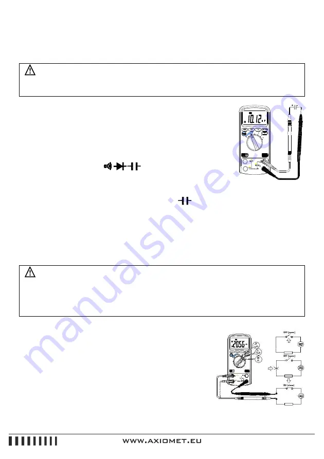
To measure capacitance (set up the Meter as shown in Figure 3-6):
1)
Set the rotary switch to
Ω
range.
Figure 3-6 Measuring Capacitance
2)
Select the auto scan mode or press the SELECT key to activate capacitance measuring mode.
3)
Connect the black and red test leads to the COM and
terminals respectively.
4)
Connect the test leads to the capacitor being measured and read the displayed value.
Note:
The meter may take a few seconds to stabilize reading when measurement on 600uF
~
60mF.
To improve the accuracy of measurement less than 600nF, subtract the residual capacitance of the
Meter and leads.
3.2.7.
Current Measurement
To avoid damage to the Meter or injury if the fuse blows, never attempt an In-circuit current
measurement where the open-circuit potential to earth is greater than 1000V.
To avoid damage to the meter, check the meter’s fuse before proceeding. Use the proper
terminals, function, and range for your measurement. Never place the probes in parallel with
a circuit or component when the leads are plugged into the current terminals.
Current is the flow of electrons through a conductor.
To measure current (set up the Meter as shown in Figure 3-7):
1)
Turn off power to the circuit. Discharge all high voltage
capacitors.
2)
Set the rotary switch to the
µ
A, mA or A range.
3)
Select the auto scan mode or press the SELECT key to select
DCA or ACA measuring mode.
Figure 3-7 Measuring Current
Summary of Contents for AX-174
Page 1: ...AX 174 INSTRUCTION...


