8
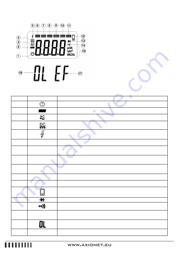
2.2. LCD Display
Figure 2-2
LCD screen is shown as in Figure 2-2, with its every symbol’s meaning shown as in the Table 1
Symbol
Meaning
1
Indicator for auto power off
2
Indicates negative readings
3
Indicator for AC voltage or current
4
Indicator for DC voltage or current
5
Unsafe voltage, voltage
≥
30V, or voltage overload (OL)
6
SCAN
When auto scan mode is selected
7
AUTO
The meter is in the Autorange mode in which the meter automatically
selects the range with the best resolution.
8
MANU
The meter is in the Manual Range mode in which the user selects the
range.
9
HOLD
When HOLD functon is enabled. When delay-hold is selected,
the HOLD symbol will be blinking for 6 seconds.
10
MAX
Display maximum data.
11
MIN
Display minimum data
12
Low battery indication (Note: When this symbol appears, it means
that the battery needs to be replaced)
13
The meter is in Diode Test mode
14
The meter is in Continuity Check mode.
15
µmVA, nµmF,
KM
Ω
Hz
Measurement units
16
This symbol means that the input is too large for the selected range
17
EF
This meter is non-contact electric field detector mode
Summary of Contents for AX-174
Page 1: ...AX 174 INSTRUCTION...


