background image

AIE500-901-FL Series U

ser’s Manual 


28 


Jumper setting & connector


3.3.10  Digital I/O Connector (CN14) (Optional) 

The AIE500-901-FL supports one 8-Channel digital I/O connector by option.  

The digital I/O is controlled via software programming. 


3.3.11  Ethernet Ports  (LAN1, LAN2) 

The  AIE500-901-FL  comes  with  two  RJ-45  connectors;  LAN1  (Intel

®

  I210-IT)  and  LAN2 

(NVIDIA

®

  JETSON

™  TX2  /  TX2i).  Ethernet  connection  can  be  established  by  plugging  one 

end  of  the  Ethernet  cable  into  this  RJ-45  connector  and  the  other  end  (phone  jack)  to  a 
1000/100/10 Base-T hub. 


Pin 

Signal 

Pin 

Signal 

DIO01 

DIO08 

DIO02 

DIO07 

DIO03 

DIO06 

DIO04 

DIO05 

+5V 

10 

GND 

Pin  1000 Base-T 

100/10 Base-T  Description 

L1 

BI_DA+ 

TX+ 

Bidirectional or Transmit Data+ 

L2 

BI_DA- 

TX- 

Bidirectional or Transmit Data- 

L3 

BI_DB+ 

RX+ 

Bidirectional or Receive Data+ 

L4 

BI_DC+ 

N.C. 

Bidirectional or Not Connected 

L5 

BI_DC- 

N.C. 

Bidirectional or Not Connected 

L6 

BI_DB- 

RX- 

Bidirectional or Receive Data- 

L7 

BI_DD+ 

N.C. 

Bidirectional or Not Connected 

L8 

BI_DD- 

N.C. 

Bidirectional or Not Connected 

LAN1: 
Active Link LED: Yellow 
Off: No link 
Blinking: Data activity detected 

LAN2: 
Speed LED:  

1000M : Yellow 

LAN1: 
Speed LED: 

1000M: Orange 

100M / 10M: Green / OFF 

LAN2: 
Speed LED: 

100M / 10M: Green / OFF 

Summary of Contents for AIE500-901-FL Series

Page 1: ...AIE500 901 FL Series Embedded System User s Manual...

Page 2: ...usefulness of any information in this document Axiomtek does not make any commitment to update any information in this manual Axiomtek reserves the right to change or revise this document and or produ...

Page 3: ...r source is correct before connecting it to any power outlet 5 Turn Off system power before cleaning Clean the system using a cloth only Do not spray any liquid cleaner directly onto the screen 6 Do n...

Page 4: ...he presence of a flammable anesthetic mixture with air oxygen or nitrous oxide 4 Mode of operation Continuous Note All of I O connectors should be connected with corresponding cables when the system i...

Page 5: ...tention to components requiring designated products for cleaning as mentioned below Cloth A piece of cloth is the best tool to use when rubbing up a component Although paper towels or tissues can be u...

Page 6: ...or recycling and we will make the proper arrangement Trademarks Acknowledgments Axiomtek is a trademark of Axiomtek Co Ltd IBM PC AT PS 2 VGA are trademarks of International Business Machines Corporat...

Page 7: ...g LTE and extra Wi Fi Antenna Cable 13 2 3 Installing the M 2 2280 Key M SSD Module 16 CHAPTER 3 JUMPER SETTING CONNECTOR 19 3 1 Jumper Connector Location 19 3 2 Jumper Setting Summary 21 3 3 Connecto...

Page 8: ...viii 3 3 17 Reset Button SW5 30 3 3 18 CMOS Battery Interface BAT1 30 3 3 19 Power and Storage LED Indicator LED 31 CHAPTER 4 JETPACK BSP FLASH METHOD 33...

Page 9: ...with NVIDIA JETSON TX2 TX2i Series supercomputer on a module to support Linux Ubuntu 16 04 and 18 04 suitable for the most endurable operation It features fanless design with full feature I O one 8GB...

Page 10: ...l O S Supported The AIE500 901 FL supports both of Linux Ubuntu 16 04 and Linux Ubuntu 18 04 Various Storage devices supported For storage device the AIE500 901 FL supports one M 2 2280 Key M with PCI...

Page 11: ...switch it supports either USB signal of PCI Express Mini Card connector or Micro USB connector For more details please refer to 3 3 Connectors One Recovery switch One Power button and one Reset butto...

Page 12: ...AIE500 901 FL Series User s Manual Introduction 4 1 3 Dimensions The following diagrams show you dimensions and outlines of the AIE500 901 FL 1 3 1 System Dimension...

Page 13: ...AIE500 901 FL Series User s Manual Introduction 5 1 3 2 Wall mount Bracket Dimension...

Page 14: ...AIE500 901 FL Series User s Manual Introduction 6 1 3 3 Din rail mount Bracket Dimension...

Page 15: ...AIE500 901 FL Series User s Manual Introduction 7 1 3 4 VESA arm mount Bracket Dimension...

Page 16: ...AIE500 901 FL Series User s Manual Introduction 8 1 4 I O Outlets The following figures show you I O outlets on front view of the AIE500 901 FL Front View drawing Rear View drawing...

Page 17: ...x 4 Screws Pack x 1 Antennas for WLAN x 2 TX2 8GB version only Regarding the latest Jetpack image product manual please download them from Axiomtek official website 1 6 Model List AIE500 901 FL Fanles...

Page 18: ...AIE500 901 FL Series User s Manual Introduction 10 This page is intentionally left blank...

Page 19: ...te Drive and PCI Express Mini Card modules The chapter 2 will show you how to install the hardware 2 1 Installing the PCI Express Mini Card Step 1 Turn off the system and unplug the power adaptor Step...

Page 20: ...t a 45 degree angle up from horizontal slowly insert the golden fingers into the PCI Express slot until it is fully inserted in Step 5 Press it down gently but firmly and then secure the PCI Express m...

Page 21: ...a Wi Fi Antenna Cable Step 1 Install the Mini PCIe card into the Mini PCIe slot and affix it with a screw For more details please refer to section 2 1 Installing the PCI Express Mini Card Step 2 Take...

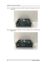
Page 22: ...es User s Manual 14 Hardware Installation Step 3 Install the antenna cable connector through the opening at the front of the chassis Step 4 Put the washer and Hex nut into the antenna cable connector...

Page 23: ...AIE500 901 FL Series User s Manual Hardware Installation 15 Step 5 Connect the antenna cable to the PCI Express mini card...

Page 24: ...the M 2 2280 Key M SSD Module Step 1 Turn off the system and unplug the power adaptor Step 2 Turn the system upside down to locate screws at the bottom side as red marked and loosen four screws Step...

Page 25: ...a 30 degree angle up from horizontal slowly insert the golden fingers into the M 2 2280 Key M slot until it is fully inserted in Step 5 Press it down gently but firmly and then secure the M 2 2280 Key...

Page 26: ...AIE500 901 FL Series User s Manual 18 Hardware Installation This page is intentionally left blank...

Page 27: ...3 JUMPER SETTING CONNECTOR Proper jumper settings configure the AIE500 901 FL to meet your application purpose We are here with listing a summary table of all jumpers and default settings for onboard...

Page 28: ...umper setting connector SBC87901 Bottom View Note We strongly recommended that you should not modify any unmentioned jumper setting without Axiomtek FAE s instruction Any modification without instruct...

Page 29: ...umpers and default settings for onboard devices respectively SBC87901 Jumper Functions Settings Port 1 Port 2 JP1 JP2 COM Port or CAN Port Settings RS 232 default JP1 3 5 JP1 4 6 JP2 3 5 JP2 4 6 CAN J...

Page 30: ...G CN1 3 3 1 DC Phoenix Power In Connector CN2 3 3 2 MicroSD Slot CN4 3 3 3 DC in Connector CN6 3 3 4 PCI Express Mini Card slot CN7 3 3 5 SIM Card Slot CN8 3 3 6 M 2 2280 Key M PCIe x1 and SATA SSD CN...

Page 31: ...gnal can be switched by Recovery Mode Switch SW1 For more details please refer to 3 3 11 Recovery Mode Switch SW1 3 3 2 DC Phoenix Power In Connector CN2 The system supports a wide range Phoenix DC in...

Page 32: ...Spec V1 2 The USB signal can be selected by Recovery Mode Switch SW1 For more details please refer to 3 3 11 Recovery Mode Switch SW1 Pin Signal Pin Signal Pin Signal Pin Signal 1 WAKE 2 3 3V 3 NC 4...

Page 33: ...Slot CN8 for inserting SIM Card In order to work properly the SIM Card must be used together with 3G LTE module which would be inserted to PCI Express Mini Card Connector CN7 It is mainly used for 3G...

Page 34: ...9 NC 20 NC 21 GND 22 NC 23 NC 24 NC 25 NC 26 NC 27 GND 28 NC 29 NC 30 NC 31 NC 32 NC 33 GND 34 NC 35 NC 36 NC 37 NC 38 M 2_DEVSLP 39 GND 40 NC 41 PEX0_RX SATA_RX 42 NC 43 PEX0_RX SATA_RX 44 NC 45 GND...

Page 35: ...nt with USB 3 1 Gen1 5Gbps and ideally for installing USB peripherals such as keyboard mouse scanner etc Pin Signal Pin Signal 1 5V_USB1 10 5V_USB2 2 USB1_D 11 USB2_D 3 USB1_D 12 USB2_D 4 GND 13 GND 5...

Page 36: ...k to a 1000 100 10 Base T hub Pin Signal Pin Signal 1 DIO01 2 DIO08 3 DIO02 4 DIO07 5 DIO03 6 DIO06 7 DIO04 8 DIO05 9 5V 10 GND Pin 1000 Base T 100 10 Base T Description L1 BI_DA TX Bidirectional or T...

Page 37: ...ponds to ttyTHS2 and COM2 corresponds to ttyTHS1 3 2 13 Debug Port Connector JP4 The JP4 is UART interface UART Port0 for debug port when developing software 3 3 14 Recovery Mode Switch SW1 It will ma...

Page 38: ...an allow users to either turn on the AIE500 901 FL or forcibly shut down the system 3 3 17 Reset Button SW5 The Reset button can allow users to reset AIE500 901 FL during system abnormal situation 3 3...

Page 39: ...ge LED Indicator LED The Yellow LED is linked to Solid state Drive SSD activity signal LED flashes every time SSD is accessed The power LED Green lights up and will remain steady while the system is p...

Page 40: ...AIE500 901 FL Series User s Manual 32 Jumper setting connector This page is intentionally left blank...

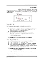
Page 41: ...oad it from FTP Untar the files and assemble the root file system with the command below sudo tar xpf imagefilename Note Please type your full image name instead of imagefilename Step3 Start flash Jet...

Reviews: