AIE500-901-FL Series U
ser’s Manual
Jumper setting & connector
23
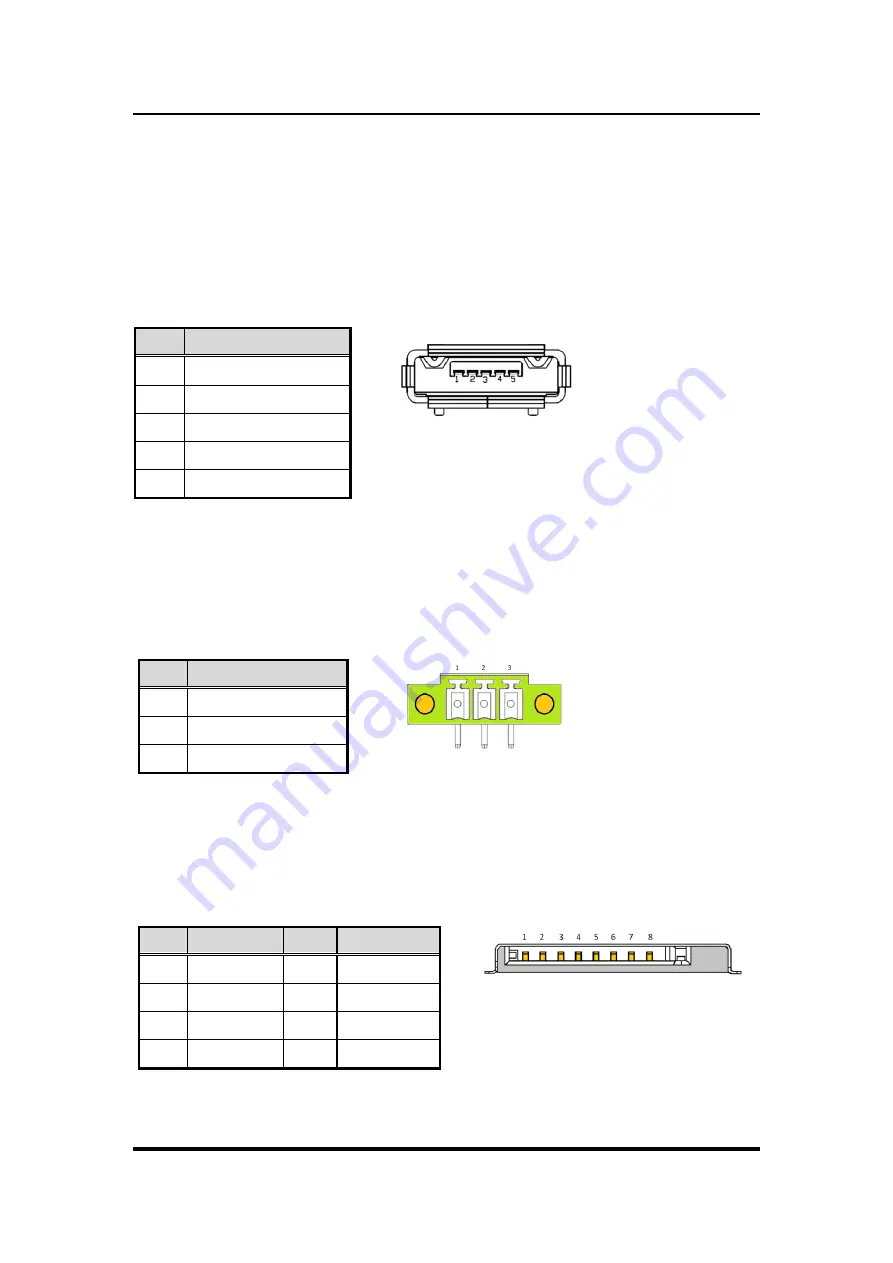
3.3.1 Micro USB 2.0 Connector (OTG) (CN1)
The CN1 is specifically designed for image flashing only. To flash Jetpack, please switching
SW1 to ON before booting up the system, which would force the system to recovery mode.
This USB signal is shared with PCI-Express Mini Card Connector (CN7), and the signal can
be switched by Recovery Mode Switch (SW1). For more details, please refer to 3.3.11
Recovery Mode Switch (SW1).
3.3.2 DC Phoenix Power In Connector (CN2)
The system supports a wide range Phoenix DC-in connector (CN2) for system power
12VDC or 24VDC input.
Pin
Signal
1
GND
2
NC
3
DCIN
3.3.3 Micro SD Slot (CN4)
The Micro Secure Digital (SD) is a flash memory card format used in portable device
including notebook and digital camera.
Pin
Signal
Pin
Signal
1
DATA1
5
+3.3VS
2
DATA0
6
CMD
3
GND
7
DATA3
4
CLK
8
DATA2
Pin
Signal
1
+5V
2
USB0 DN
3
USB0 DP
4
GND
5
GND
Summary of Contents for AIE500-901-FL Series
Page 1: ...AIE500 901 FL Series Embedded System User s Manual...
Page 13: ...AIE500 901 FL Series User s Manual Introduction 5 1 3 2 Wall mount Bracket Dimension...
Page 14: ...AIE500 901 FL Series User s Manual Introduction 6 1 3 3 Din rail mount Bracket Dimension...
Page 15: ...AIE500 901 FL Series User s Manual Introduction 7 1 3 4 VESA arm mount Bracket Dimension...
Page 18: ...AIE500 901 FL Series User s Manual Introduction 10 This page is intentionally left blank...

