GOT712S-837-24-110V User’s Manual
10
Hardware and Installation
2.5
DIO
2.5.1 Digital I/O Specification
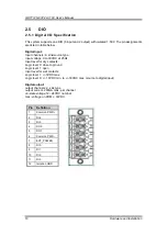
This system supports one DIO (6 input and 2 output) with isolated 1.5KV. The pin assignments
are listed in table below.
Digital Input:
Input channels: 6, sink/source type
Input voltage: 0 to 30VDC at 25Hz
Input level for dry contacts:
Logic level 0: close to ground
Logic level 1: open
Input level for wet contacts:
Logic level 1: +/-3VDC max.
Logic level 0: +/- 10VDC min. to +/-30VDC max. (source to digital input)
Digital output:
output channels: 2, sink type
output current: 200mA max. per channel
on-state voltage:12~ 24VDC nominal
max. voltage on COM+: 30VDC
Pin
Definition
1
Common PWR+
2
DI4
3
DI5
4
DO0
5
DO1
6
Common PWR-
7
EXT_POWER
8
DI0
9
DI1
10
DI2
11
DI3
12
Isolation GND
Summary of Contents for GO712S-837-R-E3845-24-110VDC
Page 1: ...GO712S 837 R E3845 24 110VDC Railway 12 1 XGA TFT LCD PANEL PC User s Manual...
Page 5: ...v 3 6 Chipset Menu 27 3 7 Security Menu 30 3 8 Boot Menu 31 3 9 Exit Menu 32...
Page 6: ...vi This page is intentionally left blank...
Page 34: ...GOT712S 837 24 110V User s Manual 28 Drivers Installation South Bridge...

