

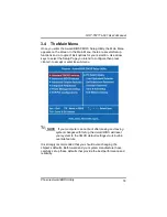
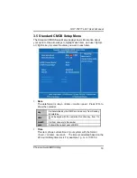

GOT-5571TL-621 User
’
s Manual
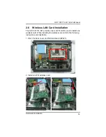
Hardware Installation
11
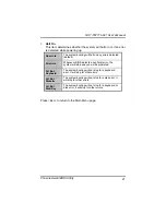
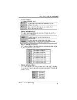
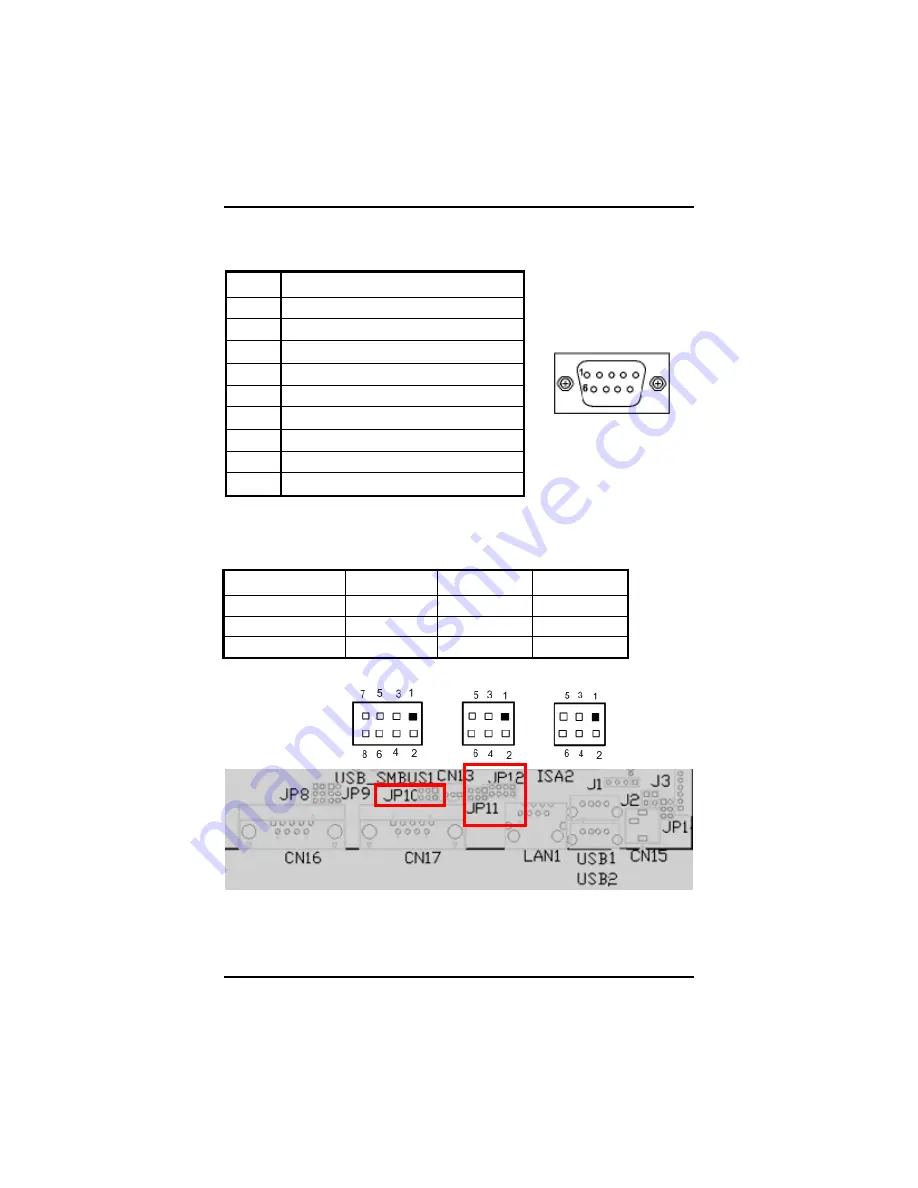
(RS-232/422/485) & COM2 (RS-232).
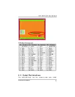
The pin assignments are listed below:
Description
1
Data Carrier Detect (DCD)
2
Receive Data (RXD)
3
Transmit Data (TXD)
4
Data Terminal Ready (DTR)
5
Ground (GND)
6
Data Set Ready (DSR)
7
Request to Send (RTS)
8
Clear to Send (CTS)
9
Ring Indicator (RI)
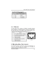
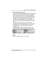
In addition, COM1 can be set for RS-232/422/485 by jumper. The jump
setting is listed as below:
COM1
JP12
JP10
JP11
RS-232 (default)
1-2
3-5, 4-6
3-5, 4-6
RS-422
3-4, 7-8
1-3, 2-4
1-3, 2-4
RS-485
5-6, 7-8
1-3, 2-4
1-3, 2-4
When COM1 set to RS-422 or RS-485, the pin assignments are listed
below:
COM2
COM1
Summary of Contents for GOT-5571TL-621
Page 1: ...i GOT 5571TL 621 5 7 VGA TFT Fanless Touch Panel Computer User s Manual ...
Page 7: ...vii 4 2 1 Specification 43 4 2 2 Driver Installation Windows XP 44 Appendix 47 ...
Page 8: ...viii MEMO ...
Page 12: ...GOT 5571TL 621 User s Manual Introduction 4 Note The unit of length is millimeter ...
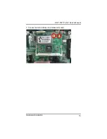
Page 21: ...GOT 5571TL 621 User s Manual Hardware Installation 13 ...
Page 49: ...GOT 5571TL 621 User s Manual Phoenix Award BIOS Utility 41 MEMO ...
Page 53: ...GOT 5571TL 621 User s Manual Installation 45 4 Select the Standard Calibrate tab ...