GOT115-319
User’s Manual
Hardware and Installation
11
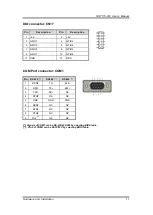
DIO connector: CN17
Pin
Description
Pin
Description
1
+5V
2
+5V
3
GPIO1
4
GPIO2
5
GPIO3
6
GPIO4
7
GPIO5
8
GPIO6
9
GPIO7
10
GPIO8
11 GND
12
GND
COM Port connector: COM1
Pin
RS232
[*]
RS422
[*]
RS485
[*]
1
DCD#
TX-
485-
2
RXD
TX+
485+
3
TXD
RX+
NC
4
DTR#
RX-
NC
5
GND
GND
GND
6
DSR#
NC
NC
7
RTS#
NC
NC
8
CTS#
NC
NC
9
RI#
[**]
NC
NC
[*]: Signals of COM1 can be RS-232/422/485 by selecting BIOS table.
[**]: Pin 9 of COM1 can be RI/5V/12V by selecting BIOS table.
Summary of Contents for GOT115-319
Page 6: ...vi This page is intentionally left blank ...
Page 10: ...GOT115 319 User s Manual 4 Introduction 1 3 Dimensions GOT115 319 outlines and dimensions ...
Page 50: ...GOT115 319 User s Manual 44 Watchdog Timer DIO Programming ...
Page 51: ...GOT115 319 User s Manual Watchdog Timer DIO Programming 45 ...


